How to Calibrate Ph Sensor
How to Calibrate Ph Sensor
In industrial process control, the accuracy of liquid analysis is as critical as the precision of level measurement. Whether managing a wastewater treatment plant, a chemical processing facility, or an oil and gas refinery, maintaining the integrity of analytical data ensures safety, compliance, and product quality. Among the various analytical instruments, the pH sensor is perhaps the most ubiquitous and, simultaneously, the most sensitive to environmental drift. Understanding how to calibrate ph sensor systems is a fundamental skill for instrumentation engineers and maintenance technicians.
Calibration is the process of adjusting the output of a measuring system to match a known standard. For pH sensors, this involves using buffer solutions with a certified pH value to define the relationship between the millivolt (mV) signal generated by the electrode and the actual pH of the process liquid. This guide provides a comprehensive technical overview of the principles, procedures, and best practices for pH sensor calibration in industrial environments.
Understanding the Principles of pH Measurement
Before diving into the calibration procedure, it is essential to understand the electrochemical principles that govern pH measurement. A standard industrial pH sensor typically consists of two main components: a glass measuring electrode and a reference electrode. These are often combined into a single "combination electrode."
The Nernst Equation
The operation of a pH sensor is based on the Nernst equation, which describes the relationship between the electric potential of the electrode and the hydrogen ion activity in the solution. The simplified version of the Nernst equation at a specific temperature is:
E = E0 – (2.303 RT / nF) × pH
Where:
* E is the measured potential (mV).
* E0 is the standard potential of the electrode.
* R is the gas constant.
* T is the absolute temperature in Kelvin.
* n is the charge of the ion (for H+, n=1).
* F is the Faraday constant.
At 25°C (298.15 K), the theoretical slope of a pH sensor is -59.16 mV per pH unit. This means that for every change of one pH unit, the sensor's output should change by approximately 59 mV. In practice, as sensors age or become contaminated, this slope deviates from the theoretical ideal. Calibration corrects for these deviations by calculating the actual slope and offset (the mV reading at pH 7.00).
Why Calibration is Mandatory
Unlike many physical sensors, such as the radar or ultrasonic level meters found on the Main Page, pH sensors are electrochemical devices that interact directly with the process medium. This interaction leads to several factors that necessitate regular calibration:
1. Electrode Aging: The sensitive glass membrane loses its responsiveness over time.
2. Coating and Scaling: Fats, oils, minerals, or biological growth can coat the membrane, slowing down the response time.
3. Reference Junction Fouling: The reference electrode requires a stable electrical path to the process. If the junction becomes clogged, the reference potential drifts.
4. Temperature Variations: pH is highly temperature-dependent. While many modern sensors include Automatic Temperature Compensation (ATC), the calibration must still account for the temperature of the buffer solutions.
Essential Equipment and Buffer Solutions for Calibration
To perform a successful calibration, specific materials are required. Using substandard or contaminated materials will lead to inaccurate results and potential process failures.
1. pH Buffer Solutions
Buffers are solutions with a known, stable pH value that resist changes in pH. In industrial settings, the most common buffers are pH 4.01, 7.00, and 10.01.
* pH 7.00 (Neutral): Used to establish the "Zero Point" or offset. At pH 7, a perfect electrode should output 0 mV.
* pH 4.01 (Acidic): Used to establish the slope in the acidic range.
* pH 10.01 (Alkaline): Used to establish the slope in the alkaline range.
2. Cleaning Agents and Deionized Water
Before calibration, the sensor must be clean. Use deionized (DI) water or distilled water for rinsing between buffer immersions. For sensors with heavy scaling, a mild hydrochloric acid (HCl) solution (approx. 2–5%) may be necessary, while protein-based coatings might require specialized pepsin cleaning solutions.
3. Temperature Measurement
Since the pH of a buffer solution changes with temperature, a calibrated thermometer or the sensor’s internal Pt100/Pt1000 RTD must be used to ensure the transmitter knows the exact temperature of the buffer during the process.
Step-by-Step Guide: How to Calibrate Ph Sensor
Most industrial transmitters support three types of calibration: single-point, two-point, and multi-point. For most applications, a two-point calibration is the standard requirement for accuracy.
Phase 1: Preparation
1. Safety First: Ensure you are wearing appropriate PPE, especially when handling acidic or alkaline process fluids.
2. Inspection: Visually inspect the sensor for cracks in the glass membrane or depletion of the reference electrolyte.
3. Cleaning: Rinse the sensor thoroughly with DI water. If there is visible buildup, follow the manufacturer's cleaning protocol. Do not wipe the glass membrane with a dry cloth, as this can create a static charge that causes erratic readings.
Phase 2: The Two-Point Calibration Procedure
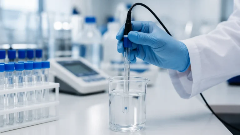
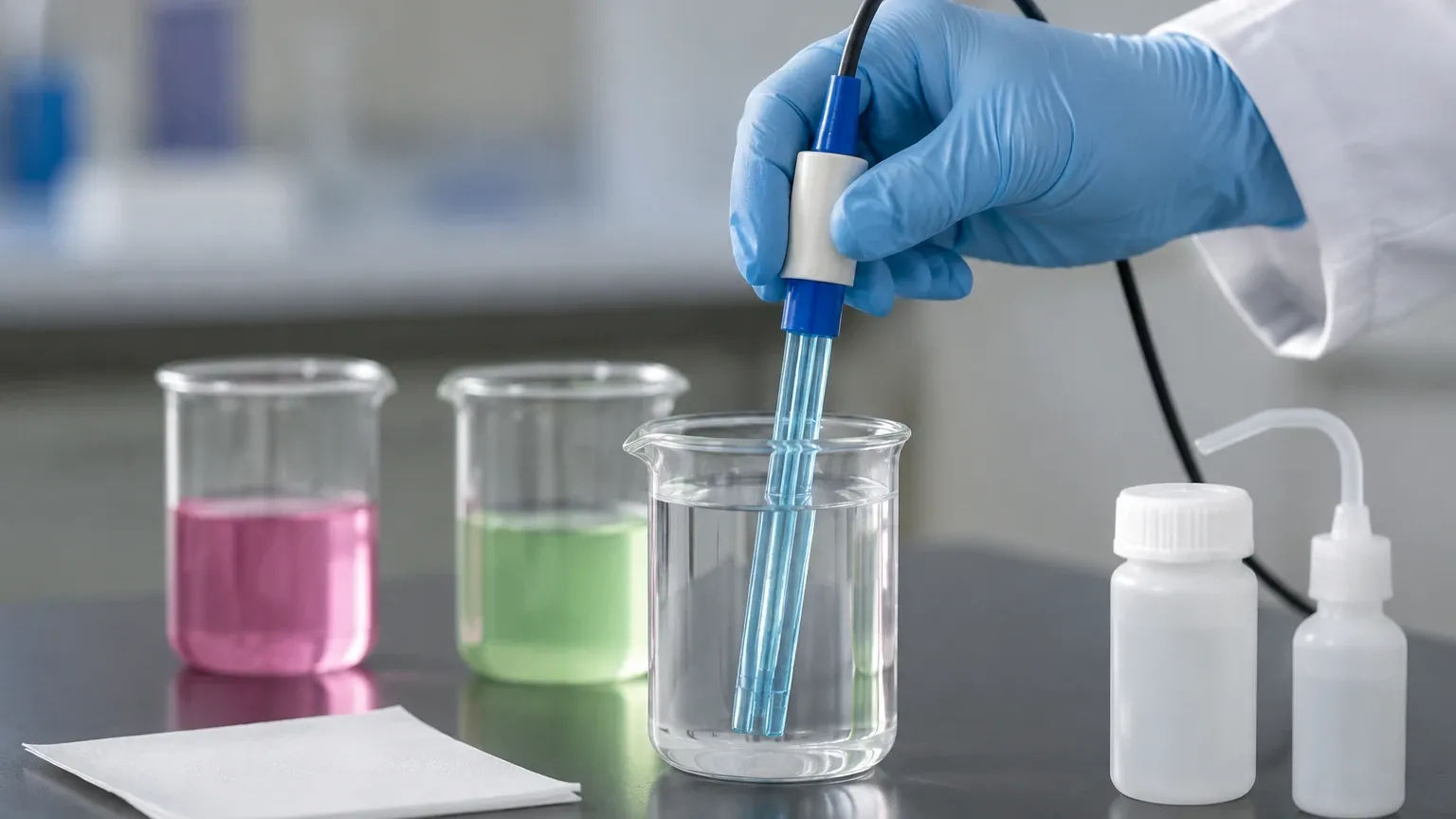
1. The Zero Point (Offset): Submerge the sensor in the pH 7.00 buffer. Allow the reading to stabilize for at least 60 to 90 seconds. The transmitter will measure the mV output. Ideally, this should be 0 mV ± 30 mV. Once stable, confirm the value on the transmitter.
2. Rinsing: Remove the sensor from the pH 7.00 buffer and rinse it with DI water. Blot (do not rub) the excess water with a lint-free tissue.
3. The Slope: Submerge the sensor in the second buffer. Choose the buffer that brackets your expected process value. If your process is acidic, use pH 4.01. If it is alkaline, use pH 10.01. Wait for the reading to stabilize. The transmitter calculates the slope as a percentage of the theoretical 59.16 mV/pH.
4. Verification: After the transmitter accepts the second point, it will display the slope and offset. A healthy sensor typically has a slope between 92% and 102%.
Phase 3: Three-Point Calibration
In applications where the process pH fluctuates across a wide range (e.g., from pH 3 to pH 11), a three-point calibration is recommended. This involves using pH 4.01, 7.00, and 10.01 buffers sequentially. This creates two distinct slope segments, providing higher accuracy across the entire scale.
Practical Selection and Comparison
Choosing the right sensor and calibration frequency depends heavily on the application. The following table compares common pH sensor configurations used in industrial automation.
| Sensor Type | Typical Application | Calibration Frequency | Maintenance Requirement |
| :— | :— | :— | :— |
| General Purpose Glass | Water treatment, cooling towers | Bi-weekly to Monthly | Low; routine cleaning |
| Teflon Junction | Chemical processing, oily water | Weekly | Moderate; junction cleaning |
| Flat Surface Electrode | Slurries, high-solids liquids | Weekly | High; physical abrasion check |
| High-Temperature Glass | Boiler feed water, sterilization | Daily to Weekly | High; electrolyte replenishment |
| HF-Resistant Glass | Semiconductor etching, mining | Weekly | Moderate; specialized glass |
When integrating these sensors into a broader system, engineers often look for comprehensive instrumentation providers. For instance, while focusing on liquid analysis, one might also require reliable level measurement solutions like those offered on the Main Page to ensure a complete view of tank or vessel status.
Factors Affecting Calibration Accuracy: Temperature and Drift
Temperature Compensation
Temperature affects pH measurement in two ways: it changes the actual pH of the solution (chemical effect) and it changes the sensitivity of the electrode (electrical effect).
Industrial pH transmitters use Automatic Temperature Compensation (ATC) to correct for the electrical effect based on the Nernst equation. However, it is a common mistake to assume ATC corrects for the chemical shift of the process liquid. If a process liquid has a pH of 7.5 at 25°C, it might naturally have a pH of 7.2 at 50°C. The sensor will correctly report 7.2, which may be misinterpreted as a process error if the temperature effect is not understood.
Signal Noise and Ground Loops
The high impedance of pH electrodes (often 100 MΩ to 1000 MΩ) makes the signal extremely susceptible to electromagnetic interference (EMI). During calibration, if the readings are jumping erratically, check for:
* Moisture in the sensor connector.
* Damaged cable shielding.
* Ground loops caused by multiple ground points in the system.
Industrial Installation and Maintenance Best Practices
How a sensor is installed significantly impacts how often you will need to ask "how to calibrate ph sensor."
1. Mounting Angle: pH sensors must be mounted at least 15° above the horizontal. This ensures that the internal bubble in the glass electrode stays at the top, keeping the membrane and reference junction wetted with electrolyte.
2. Flow Velocity: In flow-through cells, maintain a moderate flow rate. Too high a velocity can cause "streaming potentials" (noise), while too low a velocity can lead to sediment buildup.
3. Cable Routing: pH signal cables should never be run in the same conduit as high-voltage power lines. Use dedicated, shielded instrumentation trays.
4. Hydration: Never store a pH sensor in DI water. This leaches the ions out of the glass membrane and the reference electrolyte. Always store the sensor in a 3M or 4M KCl (Potassium Chloride) storage solution.
Troubleshooting Common pH Sensor Calibration Issues
Even with the correct procedure, calibration can fail. Here are the most common industrial troubleshooting scenarios:
* Slow Response Time: Usually caused by a coated glass membrane or a clogged junction. Try cleaning with a 5% HCl solution for 5 minutes, then rinse and recondition in storage solution for an hour.
* Low Slope (<85%): This indicates that the glass membrane is aging or severely contaminated. If cleaning doesn't improve the slope, the sensor likely needs replacement.
* High Offset (>±30mV): This often points to a contaminated reference junction or depleted electrolyte. Some industrial sensors allow for the replacement of the reference salt bridge; others are disposable.
* Fixed Reading (e.g., always pH 7): Check for a cracked glass membrane. A crack creates a short circuit, causing the sensor to read the internal buffer's pH (usually 7) regardless of the external environment.
Conclusion
Mastering how to calibrate ph sensor systems is vital for maintaining the accuracy of industrial liquid analysis. By following a rigorous two-point or three-point calibration routine, using fresh buffer solutions, and ensuring proper sensor cleaning, facilities can extend the lifespan of their instrumentation and ensure process stability.
In the broader context of industrial automation, pH measurement is just one piece of the puzzle. Reliable data from liquid analysis must be paired with accurate physical measurements—such as those provided by radar or hydrostatic transmitters—to achieve optimal process control. For those looking to upgrade their overall instrumentation suite, exploring the specialized measurement technologies available on the Main Page is a logical next step in optimizing industrial efficiency and safety.