Coriolis Flow Meter Pressure Drop
Coriolis Flow Meter Pressure Drop
In industrial process control, the Coriolis flow meter is often regarded as the gold standard for mass flow measurement due to its high accuracy and ability to measure multiple parameters simultaneously, including density and temperature. However, one of the most critical engineering trade-offs when selecting this technology is the coriolis flow meter pressure drop. Unlike non-intrusive technologies like ultrasonic meters or full-bore electromagnetic meters, Coriolis meters typically require the fluid to be diverted through specific tube geometries, which inherently results in a loss of fluid pressure.
Understanding and calculating this pressure drop is essential for process engineers to ensure that the system maintains sufficient head for downstream operations, avoids cavitation, and minimizes the energy costs associated with pumping. This guide provides a technical overview of the factors influencing pressure loss in Coriolis systems and how to optimize selection for industrial applications.
Measurement Principles of Coriolis Flow Meters
Before evaluating pressure drop, it is necessary to understand how these instruments function. A Coriolis flow meter consists of one or more vibrating tubes, usually driven by an electromagnetic coil. As fluid flows through the vibrating tube, the Coriolis force causes the tube to distort or twist.
The Coriolis Effect
The magnitude of this twist is directly proportional to the mass flow rate of the fluid. Sensors (pick-off coils) located at the inlet and outlet of the tubes measure the resulting phase shift in the vibration cycle. Because mass is measured directly, the instrument is not affected by changes in fluid temperature, pressure, or viscosity in the same way volumetric meters are.
Tube Geometry and Fluid Path
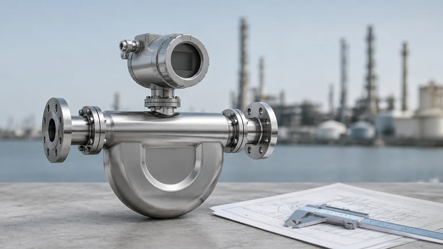
To achieve the sensitivity required for high-accuracy measurement, many Coriolis meters utilize a dual-tube design with a "U" or "S" shape. While these shapes maximize the Coriolis force for better signal-to-noise ratios, they force the fluid to change direction multiple times. Each change in direction and each reduction in the cross-sectional area of the tubes contributes to the total coriolis flow meter pressure drop.
Understanding Coriolis Flow Meter Pressure Drop
Pressure drop ($ΔP$) in a Coriolis meter is the difference between the pressure at the inlet and the pressure at the outlet. This loss is primarily composed of three factors: frictional loss, directional change loss, and expansion/contraction loss.
1. Frictional Loss: As fluid moves along the internal walls of the measuring tubes, friction converts kinetic energy into heat. This is highly dependent on the Reynolds number and the internal surface roughness of the tubes.
2. Directional Change Loss: In curved tube designs, the fluid must accelerate and decelerate as it moves through bends. This momentum change requires energy, which manifests as a drop in pressure.
3. Splitting and Recombining: Most high-capacity Coriolis meters split the flow into two parallel tubes. The transition from the main process pipe into the manifold and then into the narrower measuring tubes creates significant turbulence and pressure loss.
For engineers, managing the coriolis flow meter pressure drop is a balancing act. A smaller meter may be more sensitive and cost-effective but will induce a much higher pressure drop, potentially requiring larger pumps or leading to process instabilities.
Key Evaluation Criteria for Pressure Loss
When specifying a meter, several fluid and hardware variables must be evaluated to predict the impact on the system's hydraulic profile.
Fluid Viscosity
Viscosity is perhaps the most significant fluid property affecting pressure drop. In laminar flow regimes (common with high-viscosity fluids like oils or resins), the pressure drop increases linearly with viscosity. In turbulent flow, the relationship is more complex, but higher viscosity always results in a higher $ΔP$ for a given flow rate.
Fluid Density
Since Coriolis meters measure mass flow, the density of the fluid determines the velocity at which the fluid must travel to meet a specific mass flow target. Lower-density fluids (like gases) must travel at much higher velocities than liquids to achieve the same mass flow, often leading to substantial pressure drops in gas applications.
Flow Velocity
The pressure drop in any piping component is proportional to the square of the velocity ($V^2$). Doubling the flow rate through a Coriolis meter will approximately quadruple the pressure drop. This is why sizing a Coriolis meter based on the pipe size rather than the flow rate is a common engineering error that leads to excessive pressure loss.
Practical Selection Tables and Comparisons
When selecting a meter, engineers often compare different tube geometries. The following table illustrates the general relationship between tube design and pressure drop characteristics for a standard liquid application (water-like viscosity).
| Tube Design | Sensitivity | Pressure Drop ($ΔP$) | Typical Application |
| :— | :— | :— | :— |
| Twin U-Tube | Very High | High | General purpose, high accuracy |
| Single Straight Tube | Moderate | Low | Hygienic, low-shear, viscous fluids |
| Bent/Curved Tube | High | Moderate | Space-constrained installations |
| Large Bore (Dual) | Moderate | Medium | Bulk loading and high-volume transfer |
Sizing for Allowable $ΔP$
In most industrial B2B applications, the maximum allowable pressure drop is specified between 0.5 bar and 1.0 bar (approx. 7 to 15 psi). If the calculated coriolis flow meter pressure drop exceeds these values, a larger meter size must be selected, even if the current pipe size is smaller. This may require the use of reducers and expanders in the piping layout.
Installation Considerations to Minimize Pressure Drop
While the internal design of the meter dictates the baseline pressure loss, installation choices can influence the overall system efficiency.
* Reducers and Expanders: If the meter is smaller than the process piping, use eccentric or concentric reducers. Ensure the transitions are smooth to prevent additional turbulence.
* Orientation: For liquid service, the meter should be installed at a low point in the piping to ensure it remains full. For gas service, it should be at a high point. Entrained air in a liquid stream or condensate in a gas stream can cause erratic vibration and perceived pressure fluctuations.
* Upstream Piping: Although Coriolis meters are generally immune to flow profile disturbances, placing them immediately after a high-pressure-drop component (like a partially closed valve) can lead to cavitation within the meter tubes.
For comprehensive system integration, it is often helpful to Review product options and application support to ensure that the selected flow and level instruments are compatible with the system's hydraulic constraints.
Limitations and Common Risks
Ignoring the coriolis flow meter pressure drop can lead to several operational failures:
Cavitation and Flashing
If the pressure drop through the meter causes the local pressure to fall below the vapor pressure of the liquid, vapor bubbles will form (cavitation). As the pressure recovers at the outlet, these bubbles collapse, potentially damaging the internal tubes and causing significant measurement errors. If the pressure does not recover above the vapor pressure, the fluid remains in a gas phase (flashing), which most Coriolis meters cannot measure accurately.
Pumping Costs
In continuous processes, a high pressure drop equates to higher electricity consumption for pumps. Over a 10-year service life, the energy cost of a poorly sized Coriolis meter can exceed the initial purchase price of the instrument.
Signal Damping
In extremely high-viscosity applications, the fluid can dampen the vibration of the tubes. To overcome this, the drive gain must increase. If the pressure drop is also high, the meter may reach its operational limit, leading to a "slug flow" error or a complete loss of signal.
Frequently Asked Questions (FAQ)
Q: Can I use a Coriolis meter for gravity-fed systems?
A: It is difficult. Gravity-fed systems usually have very low available head. The coriolis flow meter pressure drop is often higher than the available pressure, which will stop or severely restrict the flow.
Q: How does gas entrainment affect pressure drop?
A: Gas bubbles in a liquid stream increase the volume and velocity of the mixture, significantly increasing the pressure drop and causing measurement instability known as "two-phase flow" noise.
Q: Is the pressure drop higher in straight-tube or bent-tube meters?
A: Generally, straight-tube meters have a lower pressure drop because the fluid path is direct. However, they may be less sensitive to low flow rates compared to U-tube designs.
Q: Does temperature affect the pressure drop?
A: Indirectly, yes. Temperature changes the viscosity and density of the fluid. For most liquids, an increase in temperature lowers viscosity, which in turn reduces the pressure drop.
Conclusion
The coriolis flow meter pressure drop is a fundamental parameter in process engineering that influences both the accuracy of the measurement and the efficiency of the overall system. By understanding the relationship between tube geometry, fluid properties, and velocity, engineers can select a meter that provides the necessary precision without compromising the hydraulic integrity of the plant.
When integrating these instruments into complex automation environments, it is vital to work with manufacturers who understand the interplay between flow, pressure, and level. For those seeking reliable industrial measurement solutions, Welk provides a range of advanced instruments tailored for demanding applications. To explore technical specifications and find the right fit for your project, visit the Main Page for detailed product information and engineering support.