
Resistance Temperature Device
Resistance Temperature Device
In the landscape of industrial process control, the resistance temperature device (RTD) stands as one of the most reliable and precise instruments for monitoring thermal conditions. Often overshadowed by the more common thermocouple, the RTD is the preferred choice for applications requiring high accuracy, stability, and repeatability over long periods. For engineers and technicians managing complex systems—ranging from chemical reactors to storage tanks—understanding the nuances of RTDs is essential for maintaining both safety and efficiency.
At its core, a resistance temperature device operates on a fundamental principle of physics: the electrical resistance of a metal changes in a predictable way as its temperature changes. By measuring this resistance, a control system can calculate the exact temperature of the medium being monitored. This article explores the technical foundations, selection criteria, and integration of RTDs within industrial environments, particularly their critical role in supporting accurate level measurement solutions.
Understanding the Resistance Temperature Device Principle
The operation of an RTD is based on the positive temperature coefficient (PTC) of metallic conductors. As the temperature of a metal increases, the thermal agitation of its atoms increases. This increased vibration impedes the flow of electrons, thereby increasing the electrical resistance.
The Linear Relationship
For most metals used in RTD construction, the relationship between temperature and resistance is relatively linear over a specific range. This relationship is mathematically defined by the Callendar-Van Dusen equation. In practical industrial applications, the most common standard is the Pt100 sensor. A Pt100 sensor is made of platinum and has a resistance of exactly 100 ohms (Ω) at 0°C (32°F). For every degree Celsius increase in temperature, the resistance of a platinum RTD increases by approximately 0.385Ω.
Sensing Elements
There are two primary types of RTD sensing elements used in the field:
1. Wire-Wound Elements: These consist of a fine platinum wire wrapped around a ceramic or glass core. They offer high accuracy and are suitable for extreme temperature ranges, though they are more susceptible to damage from high-vibration environments.
2. Thin-Film Elements: These are manufactured by depositing a thin layer of platinum onto a ceramic substrate and then etching the circuit. Thin-film RTDs are more cost-effective, more rugged, and have a faster response time, making them the standard for most modern industrial transmitters.
Material Science in RTD Construction
While several metals exhibit the resistance-temperature relationship, only a few are suitable for industrial-grade resistance temperature devices. The choice of material impacts the sensor's range, sensitivity, and cost.
| Material | Temperature Range (°C) | Characteristics |
| :— | :— | :— |
| Platinum (Pt) | -200°C to +850°C | The industry standard. Offers the best linearity, stability, and chemical resistance. |
| Nickel (Ni) | -60°C to +250°C | High sensitivity but limited range and non-linear behavior at higher temperatures. |
| Copper (Cu) | -100°C to +150°C | Excellent linearity and low cost, but prone to oxidation at higher temperatures. |
| Nickel-Iron | 0°C to +200°C | Used in specialized low-cost HVAC applications. |
Platinum is the dominant material because it remains chemically inert and provides a highly stable resistance-temperature curve over a broad range. This stability ensures that the device does not require frequent recalibration, which is a significant advantage in long-term industrial deployments.
Wiring Configurations and Signal Integrity
One of the most critical aspects of implementing a resistance temperature device is the wiring configuration. Because an RTD measures resistance, the resistance of the lead wires connecting the sensor to the control system can introduce significant errors if not properly compensated.
2-Wire Configuration
This is the simplest setup, using two wires to connect the RTD to the measuring circuit. However, the resistance of the lead wires is added directly to the sensor's resistance, leading to a constant positive error in temperature reading. This configuration is only recommended for applications where the lead wires are very short or where high precision is not required.
3-Wire Configuration
This is the most common configuration in industrial process automation. A third wire is used to measure the lead wire resistance and subtract it from the total resistance measurement. This assumes that all three wires have identical resistance, which is usually the case when using standardized multi-core cables. It provides a balance between accuracy and cost.
4-Wire Configuration
Used primarily in laboratory settings or for extremely high-precision industrial processes, the 4-wire configuration (also known as a Kelvin connection) completely eliminates the effect of lead wire resistance. Two wires carry the excitation current, while the other two measure the voltage drop across the RTD. This setup is immune to variations in lead wire resistance and length.
Integration with Level Measurement Systems
In the context of industrial automation, a resistance temperature device is rarely used in isolation. It is a vital component of integrated measurement systems, particularly in level measurement. Companies like Welk integrate temperature sensing into their Main Page of instrument offerings to ensure the accuracy of level data.
Hydrostatic Pressure Compensation
Hydrostatic level transmitters measure the pressure exerted by a liquid column to determine the level. However, the density of a liquid changes with temperature. Without an RTD to provide real-time temperature data, the level calculation would become inaccurate as the process fluid heats or cools. By integrating a resistance temperature device, the system can perform real-time density correction.
Radar and Ultrasonic Velocity Correction
In non-contact level measurement, such as ultrasonic sensors, the speed of sound is heavily dependent on the temperature of the air or gas through which the pulse travels. Similarly, in high-pressure steam applications, radar signal velocity can be affected by the dielectric properties of the medium, which are temperature-dependent. An RTD provides the necessary data to calibrate these time-of-flight measurements, ensuring millimeter-level accuracy.
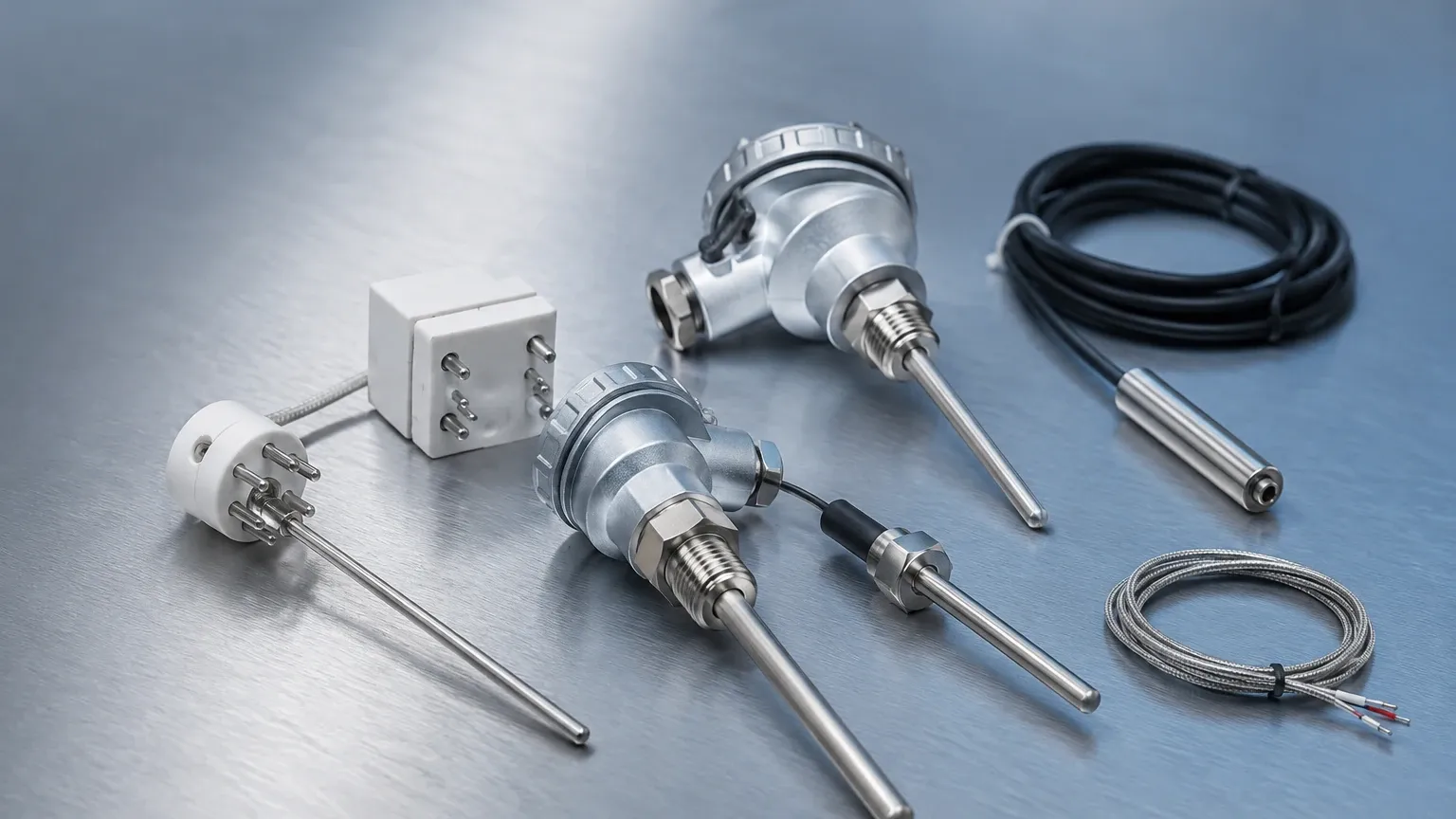
Selection Criteria and Practical Comparison
Choosing the right resistance temperature device requires an evaluation of the process environment and the required precision. The IEC 60751 standard defines the accuracy classes for platinum RTDs.
| Accuracy Class | Tolerance at 0°C | Application Suitability |
| :— | :— | :— |
| Class AA (1/3 DIN) | ±0.10°C | High-precision chemical and pharmaceutical processes. |
| Class A | ±0.15°C | Standard for most industrial process control and critical monitoring. |
| Class B | ±0.30°C | General-purpose monitoring, storage tanks, and HVAC systems. |
| Class C | ±0.60°C | Non-critical applications where approximate temperature is sufficient. |
RTD vs. Thermocouple
While thermocouples are better suited for extremely high temperatures (above 1000°C) and are faster to respond, RTDs are superior in terms of accuracy and long-term stability within their operating range. For B2B applications where process consistency is paramount, the RTD is typically the more cost-effective choice over the life of the instrument due to lower maintenance and calibration requirements.
Installation and Maintenance Best Practices
To ensure the longevity and accuracy of a resistance temperature device, proper installation is mandatory. Errors in installation are the most common cause of measurement drift and sensor failure.
1. Thermowell Selection: In high-pressure or corrosive environments, the RTD should be installed inside a thermowell. This allows the sensor to be removed for calibration without breaking the process seal. The thermowell material must be compatible with the process fluid.
2. Immersion Depth: To prevent heat conduction errors (where heat travels along the sensor sheath to the outside environment), the sensor must be immersed to a sufficient depth. A general rule of thumb is an immersion depth of at least 10 times the diameter of the sensor protection tube.
3. Self-Heating Prevention: RTDs require an excitation current to function. If the current is too high, it can cause the sensor to heat up, leading to a false high-temperature reading. Modern transmitters usually limit this current to less than 1 mA to minimize self-heating.
4. Vibration Dampening: If the application involves high-frequency vibration (such as near a pump or turbine), thin-film RTDs or specialized vibration-resistant housings should be used to prevent mechanical fatigue of the sensing element.
Limitations and Troubleshooting
Despite their robustness, resistance temperature devices have limitations. Their upper temperature limit is generally around 650°C to 850°C, beyond which the platinum can become contaminated or the insulation can break down. They also have a slower response time compared to thermocouples because of the mass of the sensing element and the protective sheath.
Common Troubleshooting Steps:
* Open Circuit: Usually indicates a broken lead wire or a failed sensing element.
* Short Circuit: Often caused by moisture ingress into the sensor housing or damaged insulation.
* Drift: Typically the result of sensor contamination or mechanical stress. If the resistance at 0°C has shifted significantly from 100°Ω, the sensor may need replacement.
Frequently Asked Questions (FAQ)
Q: How often should a resistance temperature device be calibrated?
A: In standard industrial environments, annual calibration is typical. However, for critical processes or high-vibration applications, semi-annual checks may be necessary to ensure the device remains within its accuracy class.
Q: Can I use a 2-wire RTD with a 3-wire transmitter?
A: Yes, by jumping the third terminal at the transmitter, but you will lose the lead-wire compensation, resulting in a less accurate measurement.
Q: What is the difference between Pt100 and Pt1000?
A: A Pt1000 has a resistance of 1000°Ω at 0°C. It is often used in battery-powered applications because the higher resistance allows for lower excitation current, which conserves power and reduces self-heating errors.
Q: Are RTDs suitable for sanitary applications?
A: Yes, RTDs are widely used in the food, beverage, and pharmaceutical industries. They are typically housed in polished stainless steel (316L) sheaths with tri-clamp fittings to meet hygienic standards.
By carefully selecting and installing a resistance temperature device, industrial operators can achieve the precise thermal monitoring necessary for modern process automation. Whether used for simple temperature tracking or as a compensation tool for advanced level measurement, the RTD remains a cornerstone of industrial instrumentation.


