3 Flow Meters
3 Flow Meters
In industrial process automation, the precise measurement of fluid movement is as critical as monitoring the volume stored within a vessel. While level measurement technologies—such as radar level meters and ultrasonic sensors—provide essential data on inventory and tank status, flow meters track the rate of transfer and total consumption across a facility. Selecting the correct instrument from the vast array of available technologies requires a deep understanding of fluid dynamics, pipe geometry, and the physical properties of the media.
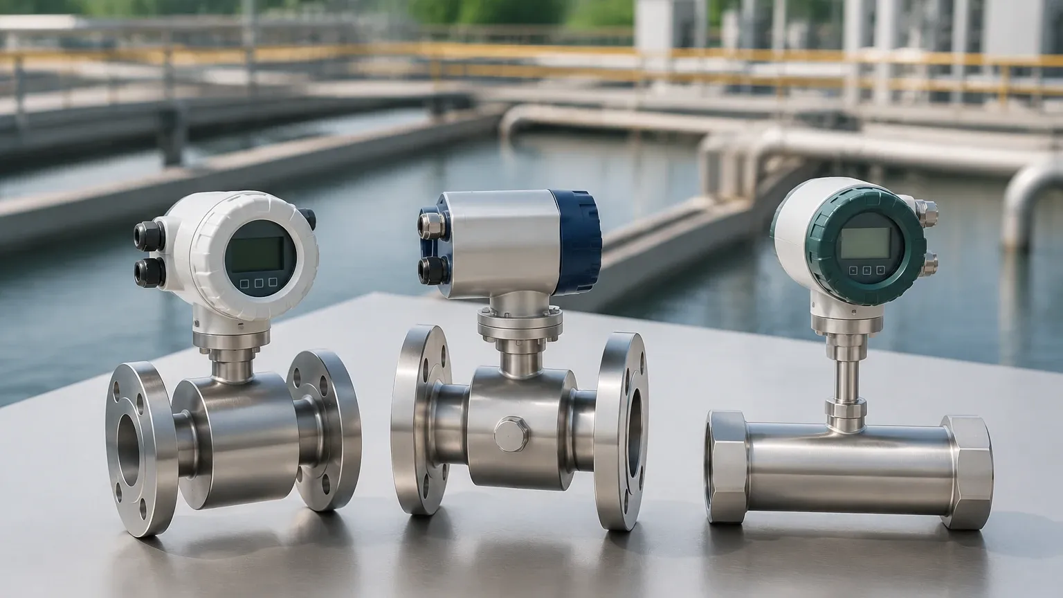
This guide examines 3 flow meters that are most commonly utilized in modern industrial applications: Electromagnetic, Ultrasonic, and Vortex flow meters. By understanding their measurement principles, selection criteria, and installation requirements, engineers can ensure high accuracy and long-term reliability in their process loops.
1. Electromagnetic Flow Meters (Magmeters)
Electromagnetic flow meters, often referred to as magmeters, are among the most versatile and widely used instruments for measuring the flow of conductive liquids. They are particularly prevalent in water treatment, chemical processing, and food and beverage industries.
Measurement Principle
Magmeters operate based on Faraday’s Law of Electromagnetic Induction. This principle states that a voltage is induced when a conductive fluid passes through a magnetic field. The device consists of a non-conductive liner (such as PTFE or PFA) and two electromagnetic coils located on the outside of the pipe. As the liquid flows through the magnetic field generated by the coils, it generates a voltage (E) that is directly proportional to the average velocity (V) of the liquid, the magnetic field strength (B), and the distance between the electrodes (D).
The mathematical representation is $E = kBDV$, where $k$ is a constant. Because the magnetic field and the pipe diameter are fixed, the induced voltage is a linear function of the flow velocity. This allows for highly accurate volumetric flow measurement regardless of changes in fluid density, viscosity, or pressure.
Applications and Limitations
Magmeters are ideal for "dirty" liquids, slurries, and corrosive chemicals because they have no moving parts and offer an unobstructed flow path. This design minimizes pressure drop and reduces the risk of clogging.
* Suitable Media: Water, wastewater, acids, bases, and conductive slurries.
* Conductivity Requirement: The fluid must have a minimum conductivity, typically $>5 μS/cm$.
* Limitations: They cannot measure non-conductive fluids like oils, deionized water, or gases.
2. Ultrasonic Flow Meters
Ultrasonic flow meters have gained significant market share due to their non-intrusive nature and the ability to measure flow without cutting into existing piping. They are categorized into two primary types: Transit-time and Doppler.
Measurement Principle
Transit-time Ultrasonic Meters: These devices use a pair of transducers that function as both transmitters and receivers. They are mounted on opposite sides of the pipe. One transducer sends an ultrasonic signal upstream, while the other sends one downstream. The signal traveling with the flow moves faster than the signal traveling against it. The difference in transit time is directly proportional to the velocity of the fluid.
Doppler Ultrasonic Meters: These rely on the frequency shift (Doppler effect) of an ultrasonic signal reflected off particles or bubbles in the flowing liquid. If the fluid is moving, the frequency of the reflected signal shifts. This shift is measured to determine the flow velocity.
Applications and Limitations
Ultrasonic meters are preferred for large-diameter pipes and applications where process downtime for installation is not feasible.
* Transit-time Use Case: Clean liquids (water, chemicals, light oils) with less than 2% suspended solids or bubbles.
* Doppler Use Case: Aerated liquids, raw sewage, and slurries where particles provide reflection points.
* Advantages: No pressure drop, no contact with the media, and high portability for clamp-on models.
* Limitations: Accuracy can be affected by pipe wall thickness, scale buildup, and flow profile disturbances.
3. Vortex Flow Meters
Vortex flow meters are the preferred choice for measuring steam, gases, and low-viscosity liquids. They are known for their robustness and ability to handle high temperatures and pressures.
Measurement Principle
Vortex meters operate on the Von Kármán effect. When a fluid flows past a "bluff body" (a non-streamlined object placed in the flow stream), it creates alternating vortices on either side of the body. These vortices are shed at a frequency that is directly proportional to the velocity of the fluid.
A sensor located behind the bluff body detects the pressure fluctuations caused by these vortices and converts them into an electrical signal. Since the frequency of vortex shedding is determined by the fluid velocity and the geometry of the bluff body, the measurement is relatively independent of fluid density or temperature, provided the Reynolds number is sufficiently high.
Applications and Limitations
Vortex meters are indispensable in power plants and heating systems for steam measurement.
* Suitable Media: Saturated and superheated steam, compressed air, nitrogen, and low-viscosity liquids like water or solvents.
* Advantages: High reliability, no moving parts to wear out, and excellent long-term stability.
* Limitations: They require a minimum flow velocity to initiate vortex shedding. At very low flow rates, the meter may read zero. They are also sensitive to pipe vibration.
Technical Selection Criteria for 3 Flow Meters
When evaluating these 3 flow meters for a specific project, engineers must compare their performance characteristics against the process requirements. The following table provides a high-level comparison:
| Feature | Electromagnetic | Ultrasonic (Transit-time) | Vortex |
| :— | :— | :— | :— |
| Primary Media | Conductive Liquids | Clean Liquids | Steam, Gas, Clean Liquid |
| Accuracy | ±0.5% to ±0.2% | ±1.0% to ±0.5% | ±1.0% (Liquid), ±1.5% (Gas) |
| Moving Parts | None | None | None |
| Pressure Drop | Zero | Zero (Clamp-on) | Moderate |
| Pipe Sizes | 3 mm to 3000 mm | 12 mm to 5000 mm | 15 mm to 300 mm |
| Installation | Inline | Inline or Clamp-on | Inline |
| Conductivity | Required (>5 μS/cm) | Not Required | Not Required |
Installation Considerations and Best Practices
To achieve the specified accuracy for any of these 3 flow meters, proper installation is paramount. The flow profile must be fully developed and laminar at the point of measurement.
1. Straight Pipe Runs: Most flow meters require a specific length of straight pipe upstream and downstream to eliminate turbulence caused by elbows, valves, or pumps. A common rule of thumb is 10D (10 times the pipe diameter) upstream and 5D downstream. For vortex meters, this requirement may increase to 20D or 30D if a control valve is located upstream.
2. Full Pipe Condition: For magmeters and ultrasonic meters, the pipe must be completely full of liquid. If the pipe is partially full, the velocity calculation will be incorrect, leading to significant measurement errors. Vertical installation with upward flow is often recommended to ensure a full pipe.
3. Grounding: Electromagnetic flow meters are sensitive to electrical noise. Proper grounding of the fluid and the meter body to a common earth ground is essential to prevent interference with the low-voltage signal induced by the flow.
4. Reynolds Number: For vortex meters, the flow must be in the turbulent regime (typically a Reynolds number > 10,000). If the flow is too slow or the fluid is too viscous, vortices will not form consistently.
Synergy Between Flow and Level Measurement
In many industrial environments, flow meters and level meters are used in tandem to provide a complete picture of the process. For example, in a chemical dosing system, a radar level meter tracks the remaining inventory in the bulk storage tank, while a magmeter ensures the precise volume of chemical is being delivered to the process line.
This integration allows for mass balance calculations, leak detection, and automated inventory replenishment. For comprehensive system integration, reviewing the Main Page of specialized instrument providers ensures compatibility between flow and level data acquisition, helping facilities optimize their industrial automation architecture.
Frequently Asked Questions (FAQs)
Q: Can a magmeter measure the flow of deionized (DI) water?
A: Generally, no. Deionized water has very low conductivity, often below the threshold required for the electromagnetic induction principle to function. An ultrasonic or vortex meter would be a better choice for DI water.
Q: Why is my ultrasonic flow meter giving inconsistent readings?
A: Inconsistent readings are often caused by poor acoustic coupling between the transducers and the pipe, or by the presence of too many air bubbles/solids in a transit-time meter. Ensure the pipe surface is clean and use a high-quality acoustic couplant.
Q: Can vortex flow meters measure wet steam?
A: Vortex meters can measure wet steam, but the presence of water droplets can cause measurement errors and potential erosion of the bluff body over time. For high-accuracy steam measurement, ensuring the steam quality is as high as possible is recommended.
Q: What is the maintenance requirement for these 3 flow meters?
A: Because all three technologies lack moving parts, maintenance is minimal. Periodic calibration checks and inspection of liners (for magmeters) or sensors (for vortex meters) for scale buildup or corrosion are the primary maintenance tasks.
Conclusion
Selecting from these 3 flow meters involves balancing the physical properties of the media with the mechanical constraints of the piping system. Electromagnetic meters offer unmatched reliability for conductive liquids and slurries; ultrasonic meters provide the flexibility of non-intrusive measurement for large systems; and vortex meters remain the industry standard for steam and gas applications. By adhering to strict installation guidelines and understanding the underlying physics of each device, process engineers can achieve the precision necessary for modern industrial efficiency.