Doppler Flow Measurement
Doppler Flow Measurement
In industrial process control, the ability to measure the velocity of fluids containing suspended solids or aerated bubbles is critical. Doppler flow measurement represents a specialized branch of ultrasonic flow sensing designed specifically for these "challenging" liquids. Unlike transit-time ultrasonic meters, which require clean fluids to function, Doppler technology thrives in environments where particles or gas pockets are present. This guide provides a technical overview of the principles, selection criteria, and installation requirements for Doppler flow measurement systems in B2B industrial applications.
Measurement Principles of Doppler Technology
Doppler flow measurement is based on the Doppler Effect, a physical phenomenon first described by Christian Doppler in 1842. In the context of fluid dynamics, the principle involves transmitting an ultrasonic signal of a known frequency into a moving liquid.
The Role of Reflectors
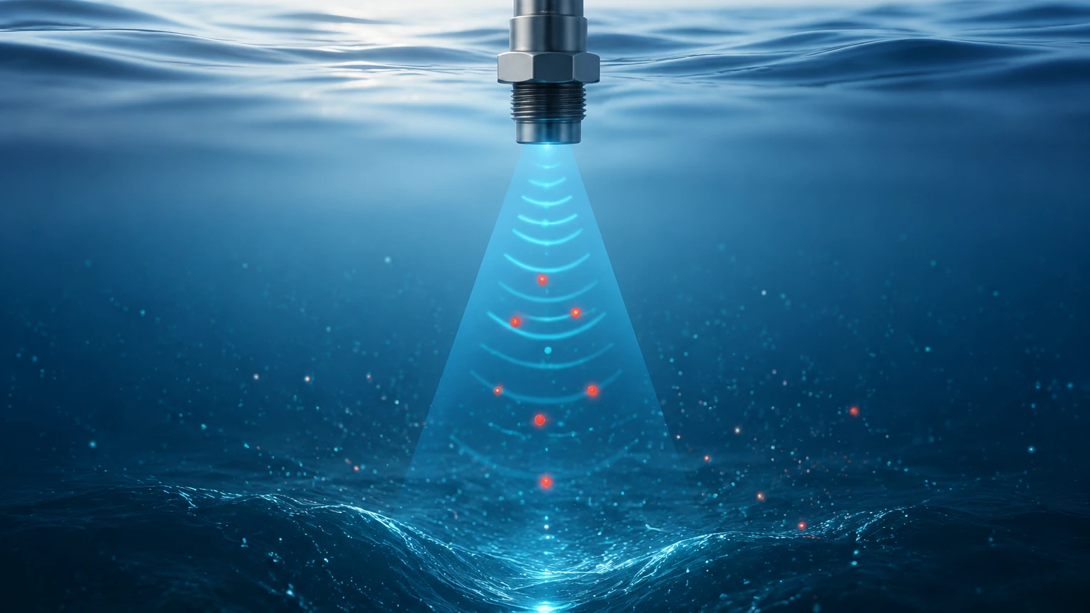
For a Doppler flow meter to function, the liquid must contain "reflectors." These are typically suspended solids, crystals, or entrained gas bubbles. When the transmitted ultrasonic beam encounters these moving particles, the signal is reflected back to a receiver.
Because the particles are moving at the same velocity as the fluid, the frequency of the reflected signal is shifted. This frequency shift is directly proportional to the velocity of the fluid. The relationship is mathematically expressed as:
Δf = 2 · fₛ · (v / c) · cos(θ)
Where:
* Δf is the frequency shift.
* fₛ is the transmitted frequency.
* v is the fluid velocity.
* c is the speed of sound in the fluid.
* θ is the angle of the ultrasonic beam relative to the pipe wall.
By measuring the difference between the transmitted and received frequencies, the instrument calculates the flow velocity. When combined with the known cross-sectional area of the pipe, the system can determine the volumetric flow rate. For comprehensive monitoring of industrial tanks and vessels, many engineers integrate these flow data points with advanced level measurement solutions found on the Main Page of specialized instrumentation providers.
Key Components of a Doppler System
A standard Doppler flow measurement system consists of two primary elements: the transducer (sensor) and the electronic converter (transmitter).
1. Transducers: These contain piezoelectric crystals. In a single-head design, both the transmitter and receiver are housed in one unit. In a dual-head design, they are separate. These can be "clamp-on" (non-invasive) or "wetted" (insertion) types.
2. Electronic Converter: This unit processes the frequency signals, performs the mathematical calculations, and provides outputs such as 4-20mA, Modbus, or HART protocols. It also handles signal filtering to ignore noise from pipe vibrations or electrical interference.
Selection Criteria and Practical Evaluation
Choosing the correct Doppler flow meter requires an understanding of the fluid characteristics and the pipe environment. The following table outlines the primary considerations for selecting a Doppler system versus other ultrasonic technologies.
Selection Table: Doppler vs. Transit-Time
| Feature | Doppler Flow Measurement | Transit-Time Measurement |
| :— | :— | :— |
| Fluid Type | Liquids with solids or bubbles | Clean liquids, low turbidity |
| Min. Particle Size | > 100 microns (typical) | N/A (requires clarity) |
| Min. Concentration | > 75 to 100 ppm | < 2% solids by volume |
| Pipe Material | Most sonically conductive materials | Most sonically conductive materials |
| Installation | Clamp-on or Insertion | Clamp-on or Inline |
| Accuracy | ±2% to ±5% of full scale | ±0.5% to ±1% of rate |
Fluid Velocity Requirements
Doppler meters generally require a minimum flow velocity to keep particles in suspension. If the velocity drops too low (typically below 0.2 m/s or 0.6 ft/s), solids may settle at the bottom of the pipe, leading to a loss of signal or inaccurate readings. Conversely, extremely high velocities can cause cavitation, which may overwhelm the sensor with too many reflectors.
Installation Considerations and Best Practices
The performance of a Doppler flow measurement system is highly dependent on proper installation. Because the technology relies on acoustic signals passing through the pipe wall and the fluid, any barrier to sound will degrade the measurement.
Pipe Orientation and Condition
* Horizontal Pipes: Sensors should be mounted at the 3 o'clock or 9 o'clock positions. Mounting at the top (12 o'clock) risks measuring air pockets, while mounting at the bottom (6 o'clock) risks measuring sediment or sludge buildup.
* Vertical Pipes: Flow should ideally be upward. This ensures the pipe is full and that reflectors are evenly distributed across the cross-section.
* Pipe Liners: Doppler signals can struggle with certain liners. If a liner is not bonded perfectly to the pipe wall (e.g., a loose plastic sleeve), an air gap will exist, which stops the ultrasonic signal. Cement, glass, or epoxy liners that are fully bonded generally allow for effective measurement.
Straight Run Requirements
To ensure a stable flow profile, Doppler meters require a specific amount of straight pipe before and after the sensor location.
* Upstream: A minimum of 10 to 20 pipe diameters (D) of straight run is recommended after elbows, valves, or pumps.
* Downstream: A minimum of 5 pipe diameters (D) is required to minimize back-pressure turbulence.
Acoustic Coupling
For clamp-on sensors, an acoustic coupling compound (grease or gel) must be applied between the sensor face and the pipe wall. This eliminates air gaps. In permanent installations, specialized adhesive couplants or mechanical tensioning straps are used to maintain the bond over years of thermal expansion and contraction.
Technical Limitations and Risks
While Doppler flow measurement is robust in dirty environments, it is not a universal solution. Engineers must be aware of the following limitations:
1. Low Reflector Concentration: If the fluid becomes too clean (e.g., a process shift from raw sewage to treated effluent), the meter will lose its signal.
2. Acoustic Attenuation: High concentrations of very fine solids (like kaolin clay) can absorb the ultrasonic energy rather than reflecting it, leading to "signal washout."
3. Velocity Profile Sensitivity: Doppler meters often measure the velocity of the particles closest to the pipe wall rather than the average velocity across the entire pipe. Modern digital signal processing (DSP) helps mitigate this, but accuracy is still generally lower than inline magnetic or transit-time meters.
4. Wall Thickness and Material: Very thick-walled pipes or pipes made of composite materials with high internal damping (like certain types of fiberglass) can attenuate the signal significantly.
Integration with Industrial Level Measurement
In many B2B applications, such as wastewater treatment or chemical processing, flow measurement is only one part of the equation. Accurate Doppler flow measurement is frequently paired with level measurement instruments to provide a complete picture of process efficiency.
For example, in open channel flow applications (like flumes or weirs), a Doppler sensor may be used to measure velocity while an ultrasonic or radar level meter measures the head height. Together, these measurements allow for the calculation of flow in non-pressurized systems. Professionals seeking high-accuracy radar or hydrostatic level transmitters to complement their flow systems can find detailed technical specifications on the Main Page of industrial instrument manufacturers.
Frequently Asked Questions (FAQ)
Q: Can Doppler flow meters measure the flow of deionized (DI) water?
A: No. Deionized water lacks the suspended solids or bubbles necessary to reflect the ultrasonic signal. A transit-time ultrasonic meter or a turbine meter would be more appropriate for this application.
Q: Does the pipe material affect the Doppler frequency shift?
A: The pipe material does not change the frequency shift itself, but it affects the signal's ability to enter the fluid. Conductive materials like carbon steel, stainless steel, and ductile iron are excellent. Heavy plastic pipes like PVC or HDPE also work well, provided they are not aerated or multilayered with air gaps.
Q: How often does a Doppler flow meter require recalibration?
A: Because Doppler meters have no moving parts, they do not suffer from mechanical wear. Recalibration is typically recommended every 1-2 years to verify the electronics and ensure that the acoustic coupling has not degraded. However, if the fluid composition changes significantly, the meter may need to be re-zeroed or adjusted for the new speed of sound in that fluid.
Q: Can Doppler sensors work on partially full pipes?
A: Standard clamp-on Doppler meters require a full pipe to provide an accurate volumetric flow rate. If the pipe is partially full, the meter will only measure the velocity of the liquid present, but it will not know the liquid level, leading to incorrect volume calculations unless integrated with a separate level sensor.
Conclusion
Doppler flow measurement remains a cornerstone technology for monitoring slurries, tailings, wastewater, and aerated chemicals. By understanding the requirement for reflectors and adhering to strict installation guidelines regarding pipe orientation and straight runs, industrial operators can achieve reliable flow data in conditions that would cause other meters to fail. When combined with robust level measurement strategies, Doppler technology ensures comprehensive control over complex industrial fluid processes.