Electromagnetic Flow Measurement
Electromagnetic Flow Measurement
In the landscape of industrial process control, electromagnetic flow measurement stands as one of the most versatile and reliable methods for quantifying the movement of conductive liquids. Often referred to as "magmeters," these instruments are essential in sectors ranging from municipal water treatment and chemical processing to food production and mining. Unlike mechanical flow meters, electromagnetic meters have no moving parts, which significantly reduces maintenance requirements and eliminates pressure drops caused by internal obstructions.
This guide provides a technical overview of the principles, selection criteria, and installation requirements for electromagnetic flow measurement, serving as a practical reference for engineers and plant operators.
Understanding the Principle of Electromagnetic Flow Measurement
The operation of an electromagnetic flow meter is based on Faraday’s Law of Electromagnetic Induction. This physical principle states that a voltage is induced when a conductor moves through a magnetic field. In the context of flow measurement, the conductive liquid serves as the conductor.
The mathematical representation of this principle is defined by the equation:
E = B × v × D
Where:
* E is the induced voltage (signal).
* B is the strength of the magnetic field.
* v is the average velocity of the liquid.
* D is the inner diameter of the pipe (the distance between the electrodes).
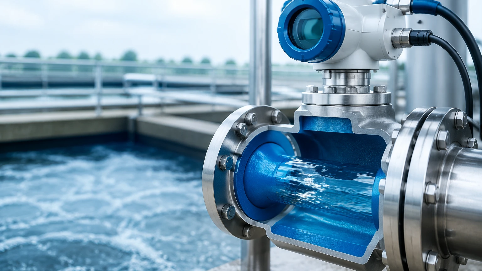
When the meter is powered, a pair of coils located inside the meter body generates a constant magnetic field across the cross-section of the flow tube. As a conductive liquid flows through this tube, it generates a voltage perpendicular to the magnetic field. This voltage is captured by two electrodes mounted on the pipe walls. Because the magnetic field strength (B) and the pipe diameter (D) are constant, the induced voltage (E) is directly proportional to the flow velocity (v). The transmitter then converts this voltage signal into a standardized output, such as 4-20mA, pulse, or a digital communication protocol (HART, Modbus).
Key Components of an Electromagnetic Flow Meter
To ensure long-term accuracy and durability, the construction of a magmeter must be compatible with the process media. The three primary components that require careful selection are the flow tube, the liner, and the electrodes.
The Flow Tube
Typically constructed from non-magnetic stainless steel, the flow tube provides the structural housing for the coils and electrodes. It must be non-magnetic to prevent interference with the generated magnetic field.
The Liner
Since the flow tube is usually metallic, an insulating liner is required to prevent the induced voltage from short-circuiting through the pipe wall. The liner material determines the meter’s resistance to temperature, pressure, and chemical corrosion. Common materials include:
* PTFE (Teflon): Excellent chemical resistance and high-temperature tolerance, but susceptible to mechanical wear in abrasive applications.
* PFA: Similar to PTFE but with better mechanical stability at high temperatures.
* Hard Rubber / Neoprene: Frequently used in water and wastewater applications for its cost-effectiveness and durability.
* Polyurethane: Highly resistant to abrasion, making it ideal for slurries and mining applications.
The Electrodes
The electrodes are the only metallic parts in direct contact with the process fluid. They must be chosen based on the chemical properties of the media to avoid corrosion or scaling. Standard materials include 316L Stainless Steel, Hastelloy C, Tantalum, and Platinum.
Technical Criteria for Selecting a Magmeter
Selecting the correct electromagnetic flow meter requires a thorough analysis of the fluid properties and the physical environment. The following table outlines the primary considerations for liner and electrode selection based on common industrial media.
Table 1: Material Selection Guide
| Application | Recommended Liner | Recommended Electrode | Notes |
| :— | :— | :— | :— |
| Potable Water | Hard Rubber / EPDM | Stainless Steel 316L | Focus on hygienic certifications. |
| Strong Acids (HCl, H2SO4) | PTFE / PFA | Tantalum / Platinum | High chemical inertness required. |
| Abrasive Slurries | Polyurethane | Hastelloy C | Requires high mechanical resistance. |
| Food & Beverage | PFA | Stainless Steel 316L | Must meet FDA/3-A standards. |
| Wastewater / Effluent | Neoprene | Stainless Steel 316L | Cost-effective for large diameters. |
Fluid Conductivity
The most critical limitation of electromagnetic flow measurement is that the fluid must be electrically conductive. Most industrial magmeters require a minimum conductivity of 5 μS/cm (microsiemens per centimeter). Consequently, magmeters cannot measure hydrocarbons (oils, fuels), distilled water, or gases.
Flow Velocity and Pipe Sizing
For optimal accuracy, the flow velocity should typically fall between 0.5 m/s and 10 m/s (1.6 ft/s to 33 ft/s). If the existing pipe size results in a velocity below 0.5 m/s, a reduced-bore meter or a smaller pipe section may be necessary to increase the velocity and improve the signal-to-noise ratio.
Installation Best Practices for Accuracy and Longevity
Even the most advanced electromagnetic flow meter will fail to provide accurate data if installed incorrectly. Engineers must adhere to specific hydraulic and electrical requirements during the design phase.
Straight Pipe Requirements
To ensure a stable flow profile, magmeters require a minimum length of straight pipe upstream and downstream of the sensor. Turbulence caused by valves, pumps, or elbows can distort the velocity profile, leading to measurement errors.
* Upstream: Minimum 5 × DN (Nominal Diameter).
* Downstream: Minimum 2 × DN.
Meter Orientation and Full Pipe Condition
The flow tube must be completely full of liquid at all times. If the pipe is partially empty, the meter will calculate the flow based on the full cross-sectional area, leading to a significant overestimation of flow.
* Vertical Installation: The preferred orientation is vertical with the flow moving upward. This ensures the pipe remains full and prevents the entrapment of air bubbles at the electrodes.
* Horizontal Installation: If horizontal installation is necessary, the electrodes should be positioned on the horizontal plane (3 o'clock and 9 o'clock positions) to avoid interference from air bubbles at the top or sediment at the bottom.
Grounding and Electrical Interference
Because the induced voltage signal is very small (often in the millivolt range), it is highly susceptible to electrical noise. Proper grounding is essential to ensure the fluid and the meter are at the same electrical potential.
* Metallic Pipes: The meter can usually be grounded directly to the pipe flanges.
* Non-Metallic / Lined Pipes: Grounding rings or a third "grounding electrode" must be used to establish a reliable electrical connection with the fluid.
Limitations and Application Boundaries
While electromagnetic flow measurement is highly robust, it is not a universal solution. Understanding its boundaries prevents costly misapplications.
1. Conductivity Requirement: As mentioned, non-conductive fluids like deionized water or petroleum-based oils cannot be measured.
2. Vacuum Conditions: Certain liners, particularly PTFE, can collapse or peel away from the tube wall if subjected to high vacuum conditions. In vacuum-prone systems, PFA liners with mechanical reinforcement are preferred.
3. Temperature and Pressure: The limits are defined by the liner material. For instance, rubber liners are generally limited to 80°C (176°F), while PFA can handle up to 180°C (356°F).
4. Magnetic Interference: High-power motors or transformers located in close proximity to the meter can interfere with the magnetic field coils, leading to unstable readings.
Integrating Flow and Level Measurement in Industrial Systems
In many industrial applications, flow measurement is used in conjunction with level measurement to provide a complete picture of process efficiency. For example, in a chemical storage tank, a radar level meter monitors the current inventory, while an electromagnetic flow meter quantifies the volume of chemicals being pumped into the production line. This dual-monitoring approach allows for mass balance calculations and leak detection.
For engineers looking to optimize their entire process loop, reviewing the full range of instrumentation is vital. For more comprehensive instrumentation options, engineers can visit the Main Page to review product options and application support. Integrating high-accuracy level sensors with reliable magmeters ensures that automated systems operate within safe and efficient parameters.
Frequently Asked Questions (FAQ)
1. Can a magmeter measure the flow of steam or air?
No. Electromagnetic flow measurement requires a conductive liquid medium. Steam and air are non-conductive and do not have the physical properties required to induce a voltage in a magnetic field.
2. What happens if the electrodes become coated with scale?
If the process fluid is prone to scaling (such as lime milk), the electrodes may become insulated from the fluid. This will lead to a signal loss or erratic readings. In such cases, meters with "removable electrodes" or ultrasonic electrode cleaning functions should be considered.
3. Does the viscosity of the liquid affect the accuracy?
Generally, no. Since the magmeter measures velocity and the magnetic field penetrates the entire cross-section, changes in viscosity do not affect the measurement, provided the flow remains within the required velocity range and the fluid is conductive.
4. Is it possible to measure bidirectional flow?
Yes, most modern electromagnetic flow transmitters are capable of measuring flow in both directions. They can be configured to provide separate totalizers for forward and reverse flow, which is particularly useful in water distribution networks.
5. Why is grounding so important for magmeters?
Grounding eliminates stray currents and ensures that the only potential difference measured by the electrodes is the one induced by the flow velocity. Without proper grounding, the signal will be buried in electrical noise, making accurate measurement impossible.
Conclusion
Electromagnetic flow measurement remains a cornerstone of industrial fluid management due to its accuracy, lack of moving parts, and compatibility with corrosive and abrasive media. By understanding the underlying principle of Faraday's Law and carefully selecting materials based on chemical and physical properties, engineers can implement a measurement solution that provides years of maintenance-free service. When designing complex fluid management systems, it is essential to source instruments from a reliable Main Page that provides both flow and level measurement solutions to ensure seamless integration and data consistency across the facility.