Gas Flow Rate Meter
Gas Flow Rate Meter
In industrial process automation, the precise measurement of gas volumes and mass is as critical as monitoring liquid levels. A gas flow rate meter is a specialized instrument designed to quantify the movement of gaseous substances through a closed conduit. Unlike liquids, gases are highly compressible, meaning their volume changes significantly with variations in temperature and pressure. Consequently, selecting and implementing the correct gas flow technology requires a deep understanding of fluid dynamics and process conditions.
For engineers and facility managers, gas flow measurement is essential for energy management (compressed air), chemical reaction control, safety monitoring (flare gas), and custody transfer. This guide examines the fundamental principles of gas flow measurement, provides selection criteria, and outlines best practices for installation and maintenance.
Measurement Principles of Gas Flow Rate Meters
Before selecting a specific instrument, it is vital to understand the physics behind the various measurement technologies. Gas flow meters generally fall into two categories: volumetric flow meters and mass flow meters.
1. Thermal Mass Flow Principle
Thermal mass flow meters operate on the principle of heat transfer. The sensor typically consists of two resistance temperature detectors (RTDs). One is heated to a constant temperature above the process gas, while the other measures the actual gas temperature. As gas flows past the heated sensor, it carries heat away. The instrument measures the electrical power required to maintain the temperature differential. Since heat dissipation is directly proportional to the number of gas molecules passing the sensor, this method provides a direct mass flow reading without needing external pressure or temperature compensation.
2. Differential Pressure (DP) Principle
This is one of the most established methods in industrial engineering. By placing a primary element—such as an orifice plate, Venturi tube, or Pitot tube—in the flow stream, a localized pressure drop is created. According to Bernoulli’s equation, the square root of the pressure difference ($ΔP$) across the restriction is proportional to the flow velocity. DP meters require secondary transmitters to compensate for changes in gas density caused by pressure and temperature fluctuations.
3. Vortex Shedding Principle
Vortex meters utilize the Von Kármán effect. When gas flows past a non-streamlined "shredder bar" (bluff body), alternating vortices are created on either side. The frequency of these vortices is directly proportional to the gas velocity. This technology is highly robust and is frequently used for high-velocity gas and steam applications where mechanical wear must be minimized.
4. Ultrasonic Transit-Time Principle
Ultrasonic gas flow rate meters use acoustic transducers to send sound pulses diagonally across the pipe. Pulses traveling with the flow move faster than those traveling against it. The difference in transit time is used to calculate the flow velocity. This non-intrusive method is highly accurate and offers a wide turndown ratio, making it a preferred choice for natural gas custody transfer.
5. Turbine Flow Principle
Turbine meters feature a rotor that spins as gas passes through the blades. The angular velocity of the rotor is proportional to the gas velocity. While highly accurate for clean gases, these meters involve moving parts and are susceptible to wear or damage from particulates or sudden gas surges.
Key Evaluation and Selection Criteria
Choosing a gas flow rate meter involves more than just matching pipe sizes. Engineers must evaluate the following parameters to ensure long-term reliability and accuracy.
Gas Composition and Properties
The chemical compatibility of the meter’s wetted parts must be verified against the process gas. For instance, corrosive gases like hydrogen sulfide ($H_2S$) require specialized alloys or coatings. Additionally, the presence of moisture (wet gas) can significantly affect the accuracy of thermal mass and ultrasonic meters.
Flow Range and Turndown Ratio
The turndown ratio is the ratio of the maximum flow to the minimum flow that the meter can accurately measure. If a process has high seasonal or operational variability (e.g., a burner that ranges from 10% to 100% capacity), a meter with a high turndown ratio, such as a thermal mass or ultrasonic meter, is required.
Accuracy vs. Repeatability
In many process control applications, repeatability (the ability of the meter to provide the same result under identical conditions) is more important than absolute accuracy. However, for billing or custody transfer, high absolute accuracy (often $\pm0.5\%$ or better) is mandatory.
Pressure and Temperature Limits
Every gas flow rate meter has specific pressure and temperature ratings. Differential pressure meters are often preferred for high-pressure applications, while specialized thermal sensors are designed for low-pressure, low-flow environments.
Technical Selection Table
| Technology | Typical Accuracy | Turndown Ratio | Primary Advantage | Common Limitations |
| :— | :— | :— | :— | :— |
| Thermal Mass | $\pm1\%$ of Reading | 100:1 | Direct mass flow; no DP loss | Sensitive to gas composition changes |
| Vortex | $\pm1\%$ of Rate | 20:1 | No moving parts; high temp | Requires minimum Reynolds number |
| Ultrasonic | $\pm0.5\%$ to $\pm1\%$ | 50:1 | No pressure drop; high accuracy | High initial cost |
| DP (Orifice) | $\pm2\%$ to $\pm3\%$ | 4:1 | Low cost; industry standard | High pressure drop; low turndown |
| Turbine | $\pm1\%$ | 10:1 | Good for high pressure | Moving parts; requires clean gas |
Installation Considerations
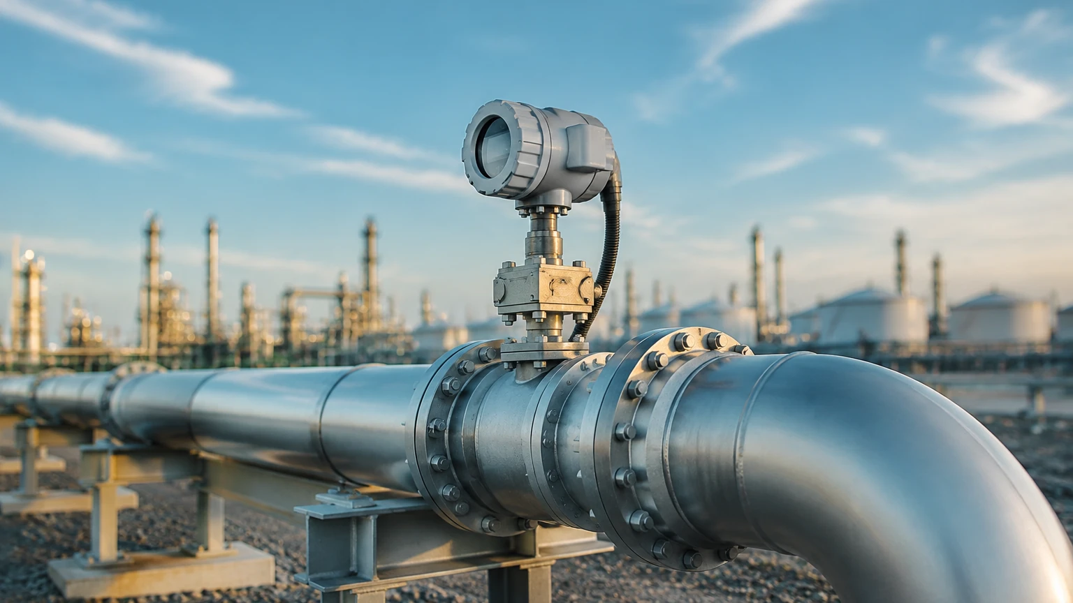
The performance of a gas flow rate meter is heavily dependent on its installation environment. Even the most expensive meter will fail to provide accurate data if installed incorrectly.
1. Straight Pipe Runs: Most gas meters require a specific length of straight pipe upstream (typically 10 to 20 diameters) and downstream (5 diameters) to ensure a fully developed, non-turbulent flow profile. If space is limited, flow conditioners or profilers may be necessary.
2. Orientation: While many meters can be installed horizontally or vertically, thermal mass meters and DP transmitters are sensitive to orientation due to potential moisture buildup or heat convection effects. Always consult the manufacturer's manual for preferred mounting positions.
3. Condensation Management: In "wet" gas applications, liquid droplets can strike sensors, causing erratic readings or physical damage. Meters should be installed at high points in the piping, or drip legs should be used to collect condensate before it reaches the instrument.
4. Vibration and Noise: Vortex and ultrasonic meters can be affected by mechanical vibration or ultrasonic noise from nearby control valves. Isolating the meter section or using noise-attenuating gaskets can mitigate these issues.
Common Risks and Limitations
When implementing gas flow measurement systems, engineers should be aware of several common pitfalls:
* Gas Compressibility Errors: If using a volumetric meter (like a turbine or DP meter), failing to account for real-time pressure and temperature changes will lead to significant mass balance errors.
* Particulate Abrasion: In industries like mining or cement production, gas streams often carry abrasive dust. This can erode orifice plates or damage turbine blades, leading to a gradual drift in measurement accuracy.
* Calibration Mismatch: Thermal mass meters are often calibrated for a specific gas mixture (e.g., 75% Methane, 25% $CO_2$). If the gas composition changes significantly, the meter must be recalibrated or updated with the new gas properties to remain accurate.
For comprehensive industrial measurement solutions, including level and flow instrumentation, engineers often refer to the Main Page of specialized manufacturers like Welk to compare technical specifications and ensure compatibility with their specific automation frameworks.
Frequently Asked Questions (FAQs)
Q: Can I use a liquid flow meter to measure gas?
A: Generally, no. Gas and liquid have vastly different densities and viscosities. While some technologies (like ultrasonic or vortex) can measure both, the internal firmware, sensor sensitivity, and calibration are specific to the fluid phase. Using a liquid-calibrated meter for gas will result in extreme inaccuracies.
Q: What is the difference between Actual Cubic Meters (ACMR) and Standard Cubic Meters (SCMR)?
A: ACMR refers to the volume of gas at the current process temperature and pressure. SCMR (or Normal Cubic Meters, $Nm^3$) refers to the volume the gas would occupy at a standard reference temperature and pressure (e.g., 0°C and 1.01325 bar). Most industrial accounting is done in Standard or Normal units.
Q: How often should a gas flow rate meter be calibrated?
A: This depends on the application and the technology. For critical custody transfer, annual calibration is standard. For general process monitoring using non-moving-part meters like Vortex or Thermal Mass, a calibration check every 2 to 3 years is often sufficient, provided there is no evidence of sensor coating or corrosion.
Q: Does pipe size affect the choice of meter?
A: Yes. For very large ducts (e.g., chimney stacks), insertion-type thermal mass or Pitot tube meters are more cost-effective than full-bore meters. For small pipes (under 25mm), inline thermal or DP meters are usually preferred.
Conclusion
Selecting the right gas flow rate meter is a balance between technical requirements and budgetary constraints. By understanding the underlying measurement principles—whether it be the heat transfer of thermal mass meters or the frequency of vortex shedding—engineers can select a device that provides reliable data for years. Proper installation, particularly regarding straight pipe runs and moisture control, remains the single most important factor in achieving the rated accuracy of the instrument. For those integrating flow measurement with tank systems, reviewing integrated solutions on the Main Page can provide further insights into holistic process monitoring.