What Is a Pressure Transducer
What Is a Pressure Transducer
In the landscape of industrial automation and process control, the ability to quantify physical forces is fundamental. Among the most critical instruments used for this purpose is the pressure transducer. While often used interchangeably with terms like "pressure sensor" or "pressure transmitter," the pressure transducer occupies a specific niche in engineering, serving as the bridge between mechanical stress and electrical data. Understanding what is a pressure transducer requires an exploration of its internal physics, its various configurations, and its indispensable role in applications ranging from hydraulic monitoring to hydrostatic level measurement.
For professional engineers and procurement specialists, selecting the right sensing technology is paramount to ensuring system longevity and accuracy. As a specialized manufacturer, Welk provides high-performance instrumentation designed to meet these rigorous industrial demands. Detailed technical specifications and product ranges can be found on the Main Page of their primary equipment portal.
Understanding the Fundamental Principles of Pressure Transduction
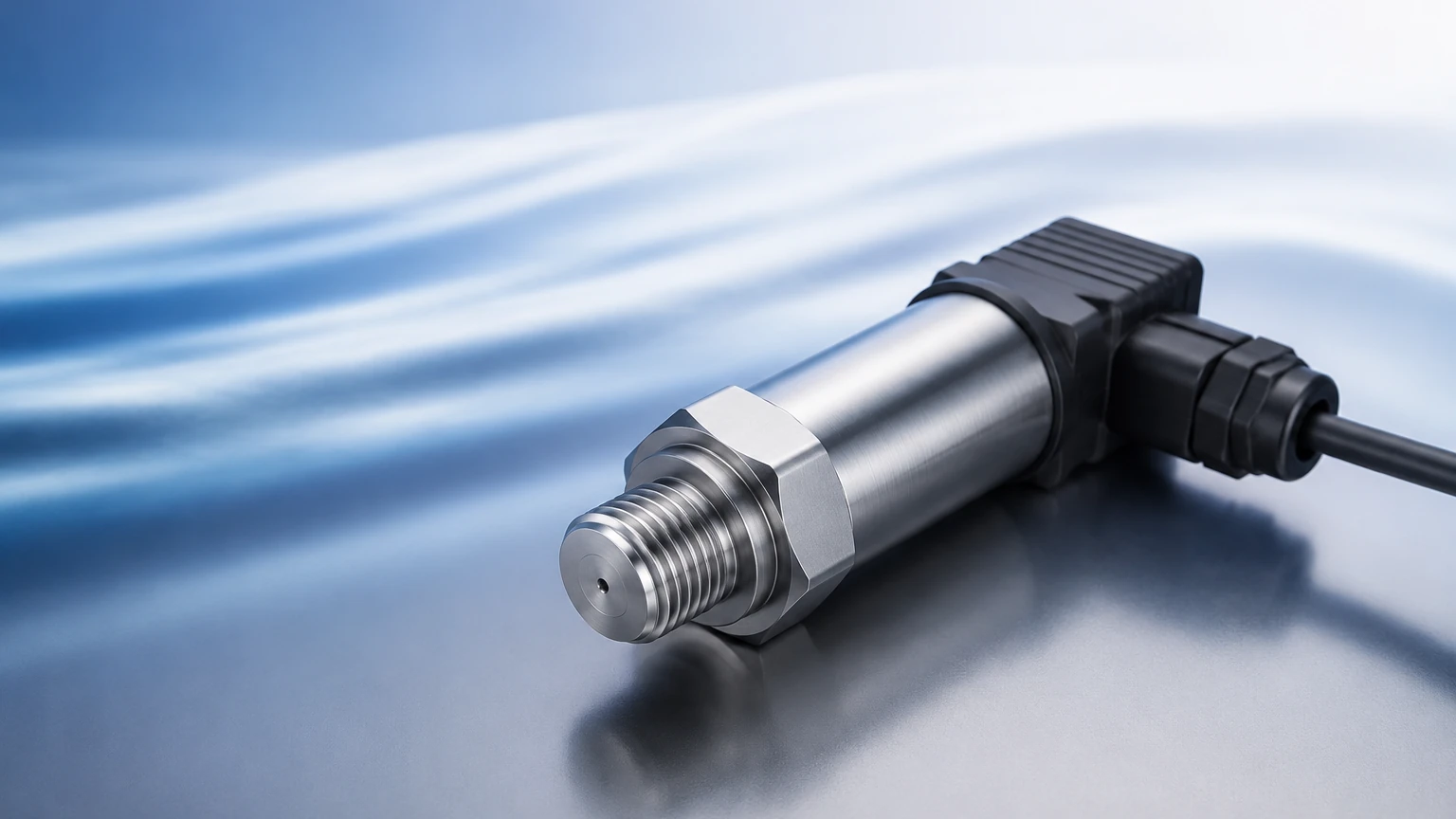
At its core, a pressure transducer is an electromechanical device that converts a mechanical pressure input into a measurable electrical output. This process typically involves two distinct stages: the primary sensing element and the transduction mechanism.
The Primary Sensing Element
The primary sensing element is usually a diaphragm, bellows, or Bourdon tube. When a fluid (liquid or gas) exerts force against this element, it undergoes a physical deformation. The magnitude of this deformation is directly proportional to the applied pressure. In modern industrial transducers, the diaphragm is the most common element due to its reliability and ability to be manufactured from various corrosion-resistant materials such as 316L stainless steel, Hastelloy, or ceramics.
The Transduction Mechanism
The transduction mechanism is the component that detects the physical movement of the diaphragm and converts it into an electrical signal. This is achieved through various physical phenomena, such as changes in electrical resistance, capacitance, or inductance. The resulting signal is typically a low-level voltage (e.g., 0-50 mV). In many industrial contexts, this signal is then conditioned and amplified by internal electronics to produce a more robust output, such as 4-20 mA or 0-10 V, at which point the device may technically be referred to as a pressure transmitter.
Primary Sensing Technologies in Industrial Transducers
Different industrial environments require different sensing technologies. The choice of technology impacts the transducer's sensitivity, thermal stability, and durability.
Piezoresistive Strain Gauges
This is the most widely used technology in industrial pressure measurement. It utilizes the piezoresistive effect, where the electrical resistance of a semiconductor or metal increases or decreases when it is mechanically strained. These gauges are typically arranged in a Wheatstone bridge circuit. When pressure deforms the diaphragm, the bridge becomes unbalanced, creating a voltage output proportional to the pressure. These sensors are known for high sensitivity and a compact form factor.
Capacitive Pressure Sensors
Capacitive transducers measure the change in electrical capacitance between a flexible diaphragm and a fixed backplate. As pressure moves the diaphragm, the distance between the plates changes, altering the capacitance. These sensors are exceptionally sensitive and are often used for measuring very low pressures. They also tend to have high overpressure capabilities and excellent long-term stability.
Piezoelectric Sensors
Unlike piezoresistive sensors, piezoelectric transducers utilize materials (like certain crystals or ceramics) that generate an electric charge when subjected to mechanical stress. These are primarily used for measuring dynamic pressure changes, such as explosions or rapid pulsations in hydraulic lines, rather than static pressures, as the charge eventually leaks away.
Pressure Reference Types: Gauge, Absolute, and Differential
To accurately interpret the data from a pressure transducer, one must understand the reference point against which the pressure is measured. There are three primary types:
1. Gauge Pressure (psig / bar g): This is the most common type. It measures pressure relative to the local atmospheric pressure. The back of the sensing diaphragm is vented to the atmosphere. This is ideal for applications like tire pressure or tank levels where the atmospheric pressure acts on both the sensor and the process media.
2. Absolute Pressure (psia / bar a): This measures pressure relative to a perfect vacuum sealed within the device. Absolute pressure transducers are essential in vacuum processes, weather monitoring, and applications where atmospheric pressure fluctuations would introduce unacceptable errors.
3. Differential Pressure (psid / bar d): These transducers have two ports and measure the difference in pressure between them. This is the standard for monitoring filter clogs (measuring pressure drop across the filter) or flow rates (using a Venturi tube or orifice plate).
The Role of Pressure Transducers in Hydrostatic Level Measurement
In the field of liquid level measurement, pressure transducers are frequently employed as hydrostatic level transmitters. This application relies on the principle that the pressure at the bottom of a liquid column is directly proportional to the height of the liquid and its density.
The mathematical relationship is expressed as:
P = ρ × g × h
Where:
* P is the hydrostatic pressure (Pascals or bar).
* ρ (rho) is the density of the liquid (kg/m³).
* g is the acceleration due to gravity (approximately 9.81 m/s²).
* h is the height of the liquid column (meters).
For a tank containing water (density ~1000 kg/m³), every 1 meter of depth exerts approximately 9.8 kPa (0.098 bar) of pressure. By installing a pressure transducer at the bottom of a tank, or submerging a probe-style transducer, the liquid level can be calculated with high precision. Welk specializes in these hydrostatic solutions, providing submersible sensors with specialized vented cables to ensure accurate gauge pressure readings even in deep wells or large reservoirs.
Technical Selection Criteria for Industrial Applications
Selecting a pressure transducer requires a detailed analysis of the process conditions. The following table provides a comparison of common evaluation criteria for different transducer types:
| Selection Factor | Piezoresistive (Silicon) | Ceramic Capacitive | Thin Film Strain Gauge |
| :— | :— | :— | :— |
| Accuracy | High (0.1% to 0.25%) | Very High (0.05% to 0.1%) | Moderate (0.25% to 0.5%) |
| Pressure Range | Low to Medium | Very Low to Medium | Medium to Very High |
| Media Compatibility | Requires isolation diaphragm | Excellent (Corrosion resistant) | Good |
| Temperature Stability| Moderate (Requires compensation) | High | Excellent |
| Overpressure Limit | Moderate | High | Moderate |
| Common Use Case | General industrial, HVAC | Chemical processing, Food/Bev | Hydraulics, Heavy machinery |
Key Confirmation Points Before Purchase
Before finalizing a selection, engineers should confirm the following parameters:
* Pressure Range: The operating pressure should ideally fall within 50% to 75% of the transducer's full-scale range to ensure accuracy and prevent damage from spikes.
* Wetted Materials: Ensure the diaphragm and housing materials are compatible with the process media (e.g., using Hastelloy for acidic environments).
* Output Signal: Determine if the control system requires 4-20 mA (best for long distances), 0-10 V, or digital protocols like Modbus RS485 or HART.
* Process Temperature: Standard transducers usually operate up to 80°C (176°F). Higher temperatures require cooling elements or specialized high-temp sensors.
Installation Best Practices and Environmental Considerations
Correct installation is as critical as the selection of the device itself. Even the most accurate pressure transducer will provide faulty data if installed improperly.
Mounting and Orientation
While many transducers are orientation-independent, low-pressure models can be affected by the weight of the diaphragm if rotated. It is best practice to calibrate the zero point in the final mounting position. For liquid applications, the sensor should be mounted below or at the same level as the tap to avoid air pockets. For gas applications, it should be mounted above the tap to allow moisture to drain back into the process.
Venting and Moisture Protection
For gauge pressure transducers, a vent is necessary to reference atmospheric pressure. In submersible level applications, this vent is typically a small tube running inside the cable. It is vital to protect this vent from moisture and debris using a desiccant filter or a specialized breathing bag, as water entering the vent tube can cause permanent internal damage and measurement drift.
Signal Integrity
To prevent electromagnetic interference (EMI), shielded cables should be used, and the shield should be grounded at only one end (typically the controller end) to avoid ground loops. In hazardous areas, intrinsically safe barriers or explosion-proof housings are mandatory to meet ATEX or IECEx standards.
Limitations and Maintenance of Pressure Sensing Equipment
While pressure transducers are robust, they are not without limitations. Understanding these risks allows for better system design and maintenance scheduling.
1. Pressure Spikes and Water Hammer: Sudden changes in valve position or pump starts can create pressure transients far exceeding the transducer's burst pressure. Using pressure snubbers or capillary tubes can dampen these spikes.
2. Temperature Drift: All transducers exhibit some degree of thermal sensitivity. While modern units include internal compensation, extreme temperature swings can still affect the zero-point stability.
3. Clogging and Fouling: In wastewater or viscous chemical applications, the small pressure ports of standard transducers can become clogged. In these cases, a "flush diaphragm" design is recommended to prevent buildup.
4. Long-term Drift: Over years of service, the mechanical properties of the diaphragm may change slightly. Periodic calibration—typically once a year—is recommended to maintain system accuracy.
Frequently Asked Questions (FAQ)
Q: What is the difference between a pressure transducer and a pressure transmitter?
A: Technically, a transducer converts pressure into a low-level voltage signal (mV), while a transmitter includes additional electronics to convert that signal into a standardized current loop (4-20 mA) or a higher-level voltage (0-10 V) suitable for long-distance transmission.
Q: Can I use a pressure transducer to measure the level of a pressurized tank?
A: Yes, but you must use a differential pressure transducer. One port measures the total pressure at the bottom (liquid + headspace gas), and the other port measures the headspace gas pressure only. The device then subtracts the gas pressure to provide the true liquid level.
Q: How do I choose between a stainless steel and a ceramic diaphragm?
A: Stainless steel (316L) is the standard for most clean liquids and gases. Ceramic diaphragms are preferred for abrasive media or highly corrosive chemicals where stainless steel might fail, as ceramics offer superior chemical inertia and hardness.
Q: Why is 4-20 mA the most common output for these devices?
A: The 4-20 mA current loop is highly resistant to electrical noise and can travel over long distances without signal loss. Furthermore, the "live zero" (4 mA) allows the system to distinguish between a zero-pressure reading and a broken wire (0 mA).
For engineers looking to integrate these technologies into their specific process environments, consulting with a specialized manufacturer like Welk ensures that the selected instrument matches the technical requirements of the application. Explore their full range of industrial level and pressure measurement tools on the Main Page.