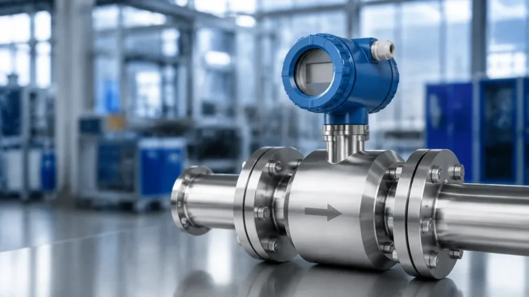
Mass Flow Meters and Controllers
Mass Flow Meters and Controllers
In modern industrial processing, the transition from volumetric flow measurement to mass flow measurement represents a significant step toward higher precision and process stability. While volumetric flow is susceptible to changes in temperature and pressure, mass flow remains constant regardless of environmental variables. This article provides a technical overview of mass flow meters and controllers, their operating principles, and how they integrate into broader process control systems alongside level measurement technologies.
Understanding the Need for Mass Flow Measurement
In B2B industrial environments, such as chemical manufacturing, pharmaceutical production, and oil and gas refining, the mass of a substance is often the most critical variable. For example, in a chemical reaction, stoichiometric ratios are based on mass, not volume. If a gas is measured by volume, a slight increase in pressure would compress the gas, leading to an inaccurate count of the actual number of molecules entering the reactor.
Mass flow meters and controllers eliminate the need for separate temperature and pressure compensation calculations. By measuring the mass directly, these instruments provide a reliable data point for mass balance, which is essential for both quality control and safety. When paired with high-precision level sensors—such as those found on the Main Page of industrial instrumentation providers—engineers can achieve a comprehensive view of material movement and storage inventory.
Core Measurement Principles
There are two primary technologies used in mass flow measurement: Thermal Dispersion and Coriolis. Each has distinct advantages depending on the medium and the required accuracy.
1. Thermal Mass Flow Meters
Thermal mass flow meters are primarily used for gas applications. They operate based on the principle that a fluid will carry heat away from a heated surface at a rate proportional to its mass flow rate.
* Constant Temperature Differential: The sensor consists of two RTDs (Resistance Temperature Detectors). One RTD measures the ambient temperature of the gas, while the other is heated to a specific, constant temperature above the ambient. As gas flows over the heated sensor, it cools down. The instrument measures the electrical power required to maintain the temperature differential. This power is directly proportional to the mass flow rate.
* Applications: Ideal for compressed air monitoring, nitrogen blanketing, and natural gas measurement where the gas composition is known and consistent.
2. Coriolis Mass Flow Meters
Coriolis meters are considered the "gold standard" for mass flow because they measure mass directly without relying on thermal properties. They are suitable for both liquids and gases.
* The Coriolis Effect: The meter contains one or more vibrating tubes. When a fluid (liquid or gas) flows through these tubes, the mass of the fluid in motion causes a shift or "twist" in the vibration of the tubes due to inertia. This phase shift is detected by sensors at the inlet and outlet. The magnitude of the phase shift is directly proportional to the mass flow rate.
* Added Benefits: Because the vibration frequency of the tubes changes with the density of the fluid, Coriolis meters can simultaneously measure mass flow, density, and temperature.
Mass Flow Controllers (MFCs)
While a mass flow meter simply monitors the flow, mass flow meters and controllers differ in that the controller includes a built-in mechanism to actively regulate the flow. An MFC consists of three main components:
1. The Sensor: A mass flow measurement element (usually thermal).
2. The Control Valve: Typically a proportional solenoid valve or a piezo-actuated valve.
3. The Electronics: A closed-loop PID (Proportional-Integral-Derivative) control circuit.
When a user provides a "setpoint" (a desired flow rate), the electronics compare the actual flow from the sensor to the setpoint. If there is a discrepancy, the controller adjusts the valve position in milliseconds to reach and maintain the target mass flow. This is critical in applications like semiconductor wafer fabrication, where precise gas mixing is mandatory.
Selection Criteria for Industrial Applications
Choosing between different mass flow meters and controllers requires an evaluation of the fluid properties and the environmental conditions. Use the following table as a preliminary selection guide:
| Feature | Thermal Mass Flow | Coriolis Mass Flow |
| :— | :— | :— |
| Primary Medium | Gases only (typically) | Liquids, Slurries, and Gases |
| Accuracy | ±1% to ±2% of full scale | ±0.1% to ±0.5% of rate |
| Pressure Drop | Very Low | Moderate (depends on tube design) |
| Direct Density Measurement | No | Yes |
| Sensitivity to Vibration | Low | High (requires careful mounting) |
| Cost | Economical | High Investment |
| Typical Pipe Sizes | 10 mm to 4000 mm (insertion) | 1 mm to 300 mm |
Installation Considerations
To ensure the accuracy of mass flow meters and controllers, specific installation protocols must be followed:
* Straight Pipe Runs: Thermal mass flow meters generally require significant straight pipe runs (typically 10 to 20 diameters upstream and 5 diameters downstream) to ensure a fully developed flow profile. If space is limited, flow conditioners or honeycombs may be necessary.
* Orientation: For Coriolis meters, the orientation depends on the fluid. For liquids, the tubes should point downward (to avoid trapping gas bubbles). For gases, the tubes should point upward (to avoid trapping condensate).
* Vibration Isolation: Coriolis meters are sensitive to external mechanical vibrations. They should be mounted on rigid supports and isolated from pumps or vibrating machinery using flexible couplings if necessary.
* Cleanliness: MFCs, particularly those used in specialty gas applications, are sensitive to particulates. Installing a 10-micron filter upstream is standard practice to prevent valve clogging or sensor drift.
Synergy with Level Measurement
In many process plants, mass flow data is cross-referenced with level measurement data to ensure system integrity. For instance, in a storage tank equipped with a radar level meter or a hydrostatic level transmitter (technologies detailed on the Welk Main Page), the change in level over time should correlate exactly with the mass flow entering or exiting the vessel.
If a Coriolis meter indicates that 500 kg of acid has been pumped into a tank, but the level sensor shows an increase equivalent to only 450 kg, this discrepancy alerts operators to potential leaks, calibration errors, or unexpected changes in fluid density. This "mass balance" approach is a cornerstone of modern industrial automation and safety.
Limitations and Risks
Despite their precision, mass flow instruments have limitations that engineers must manage:
1. Gas Composition Changes: Thermal mass flow meters are calibrated for a specific gas or gas mixture. If the composition changes (e.g., a change in the ratio of Nitrogen to CO2), the thermal conductivity of the gas changes, leading to significant measurement errors.
2. Moisture and Condensation: In thermal meters, water droplets hitting the heated sensor can cause "spikes" in the reading as the sensor attempts to evaporate the liquid. Proper knockout pots or dryers are required for wet gas applications.
3. Pressure Limits: While mass flow is independent of pressure for measurement, the physical housing of the meter and the control valve in an MFC have maximum pressure ratings (often up to 100 bar or 700 bar for specialized units) that must not be exceeded.
Frequently Asked Questions (FAQ)
Q: Do mass flow meters require frequent recalibration?
A: It depends on the application. For custody transfer or high-purity chemical dosing, annual calibration is standard. However, for stable processes like compressed air monitoring, a check every 2-3 years may suffice. Always check for "zero drift" periodically.
Q: Can a Coriolis meter measure two-phase flow (gas and liquid mixed)?
A: Standard Coriolis meters struggle with "slug flow" or high gas-void fractions, as the bubbles dampen the tube vibration. However, advanced digital signal processing (DSP) in newer models can handle entrained gas up to a certain percentage (usually <10%).
Q: What is the turndown ratio for mass flow controllers?
A: Most high-quality MFCs offer a turndown ratio of 50:1 or 100:1. This means a controller with a full scale of 100 Ln/min can accurately control flow down to 1 or 2 Ln/min.
Conclusion
Integrating mass flow meters and controllers into an industrial process provides the precision necessary for high-value manufacturing and efficient resource management. By understanding the underlying physics—whether thermal or Coriolis—and ensuring proper installation, facilities can minimize waste and maximize throughput. For comprehensive process control, these flow solutions should be implemented as part of a broader instrumentation strategy that includes reliable level, pressure, and temperature monitoring. For more information on complementary level measurement technologies, visit the Main Page for technical specifications and application support.