Radar Level Transmitter Probe
Radar Level Transmitter Probe: An Engineering Guide to Selection and Application
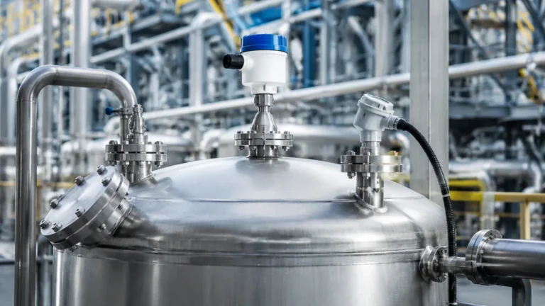
In the landscape of industrial process automation, the accuracy of level measurement directly impacts operational safety, inventory management, and process efficiency. Among the various technologies available, Radar Level Meters have emerged as a primary choice for engineers due to their high precision and lack of moving parts. Central to the performance of these systems is the radar level transmitter probe, the physical component responsible for directing or emitting electromagnetic signals to the product surface.
Selecting the correct radar level transmitter probe requires a deep understanding of electromagnetic wave propagation, the physical properties of the media, and the mechanical constraints of the vessel. This guide provides a technical overview of radar measurement principles, probe geometries, and practical selection criteria for B2B industrial applications.
Understanding Radar Measurement Principles
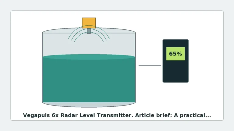
Radar level measurement relies on the transmission of high-frequency electromagnetic waves (microwaves). These waves travel at the speed of light and are reflected back to the sensor when they encounter a change in the dielectric constant ($ε_r$) of the medium. The time elapsed between transmission and reception—the Time of Flight (ToF)—is used to calculate the distance to the material surface.
Time of Flight (ToF) and FMCW
Most modern radar level transmitter probes utilize one of two processing methods:
1. Pulse Radar: The sensor emits a short microwave pulse and measures the time it takes to return. This is energy-efficient and suitable for many standard applications.
2. Frequency Modulated Continuous Wave (FMCW): The sensor emits a continuous signal with a varying frequency. The distance is determined by the frequency difference between the transmitted and received signals. FMCW generally offers higher accuracy and better signal-to-noise ratios in complex environments.
Guided Wave Radar (GWR) vs. Non-Contact Radar
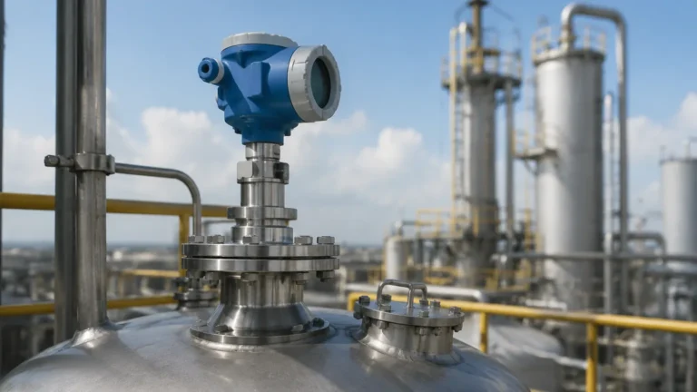
The term "probe" is most frequently associated with Guided Wave Radar (GWR). In GWR systems, the microwave signal is conducted along a physical probe (a rod or cable). This prevents signal dispersion and allows for reliable measurement even in narrow tanks or media with low dielectric constants.
Conversely, Non-Contact Radar uses an antenna (often referred to as a lens or horn antenna) to broadcast waves through the air. While non-contact systems are ideal for corrosive or extremely hot media, the GWR radar level transmitter probe is preferred when foam, turbulence, or internal tank obstructions are present.
Types of Radar Level Transmitter Probes
The geometry of the probe determines how the electromagnetic field is distributed and how sensitive the instrument is to external interference.
1. Single Rod Probes
Single rod probes are the most common choice for liquids and clean fluids. They are easy to install and less prone to material build-up than more complex designs. They are typically available in lengths up to 6 meters (approx. 20 feet).
2. Wire Cable Probes
For tall silos or deep tanks, a flexible stainless steel cable is used as the probe. These can extend up to 30 or 75 meters depending on the manufacturer's specifications. A weight at the bottom keeps the cable taut. These are essential for bulk solids like grain, cement, or plastic pellets.
3. Coaxial Probes
Coaxial probes consist of a central rod inside an outer tube. The electromagnetic field is entirely contained within the tube, making the measurement immune to tank internals, nozzles, or the tank wall. This is the most accurate probe type and is ideal for low-dielectric liquids like liquefied gases or oils, though it is susceptible to clogging if the media is viscous or contains solids.
4. Double Rod/Cable Probes
These utilize two parallel conductors. They offer a stronger signal return than single rods and are often used for liquids with lower dielectric constants where a coaxial probe cannot be used due to viscosity concerns.
Technical Selection Criteria
When specifying a radar level transmitter probe, engineers must evaluate several variables to ensure long-term reliability.
Dielectric Constant (ε_r)
The dielectric constant is the most critical factor. It represents the ability of the material to reflect microwave energy.
* High ε_r (>10): Water-based liquids provide strong reflections.
* Low ε_r (1.4 to 4): Hydrocarbons and solvents reflect poorly. GWR probes are often required to "guide" the signal and ensure enough energy returns to the sensor.
Process Conditions
* Temperature: Standard probes handle up to 150°C, but specialized high-temperature versions with ceramic seals can withstand over 400°C.
* Pressure: Probes must be rated for the vessel's maximum operating pressure, often ranging from vacuum to 40 MPa (400 bar).
* Corrosivity: For aggressive chemicals, probes are often coated in PFA or PTFE, or manufactured from exotic alloys like Hastelloy or Tantalum.
Probe Selection Table
| Probe Type | Best For | Max Range (Typical) | Limitations |
| :— | :— | :— | :— |
| Single Rod | Liquids, bypass chambers | 6m | Sensitive to nozzle interference |
| Single Cable | Solids, tall silos | 75m | Requires bottom anchoring in turbulence |
| Coaxial | Low dielectric liquids, LPG | 6m | Not for viscous or dirty fluids |
| PTFE Coated | Acids, corrosive chemicals | 6m | Temperature limited by coating |
Installation Considerations and Constraints
Correct installation is paramount to avoid "false echoes"—reflections from tank walls or internal structures that the transmitter might mistake for the product level.
1. Nozzle Dimensions: The nozzle diameter and height can affect the signal. For GWR, the probe should ideally be centered in the nozzle. For non-contact radar, the antenna should extend slightly past the nozzle bottom to prevent signal ringing.
2. Obstructions: Probes should be installed away from agitators, ladders, and inflow pipes. If an obstruction is unavoidable, many Radar Level Meters feature "False Signal Suppression" software to map out and ignore these static reflections.
3. The Dead Zone (Blocking Distance): Every radar level transmitter probe has a "dead zone" at the top (near the flange) and sometimes at the bottom (near the weight or end of the rod). Measurement is not possible in these areas. Engineers must account for this when calculating the maximum fill level.
4. Mounting Angle: The probe must be mounted vertically. Even a few degrees of tilt can significantly degrade signal quality in GWR or cause the signal to miss the receiver in non-contact applications.

Application Risks and Limitations
While highly versatile, radar technology is not a universal solution. Engineers should be aware of the following risks:
* Heavy Foam: Extremely dense, thick foam can absorb microwave signals rather than reflecting them. In such cases, a GWR probe with a low-frequency setting may be necessary, or a different technology like a magnetic level gauge might be required.
* Build-up and Bridging: In GWR cable probes used for solids, material can "bridge" between the probe and the tank wall, or coat the probe heavily. This can cause the signal to track the build-up rather than the actual level.
* Condensation: While radar can see through vapor, heavy condensation on the antenna or the top of the probe can attenuate the signal. High-frequency (80GHz) non-contact radars with lens antennas are specifically designed to shed droplets and minimize this effect.
International Procurement: What to Confirm
When sourcing a radar level transmitter probe for international projects, buyers should confirm the following with the manufacturer:
1. Certification: Ensure the device meets local hazardous area requirements (ATEX, IECEx, or UL/CSA).
2. Process Connection: Confirm thread types (NPT vs. BSP) or flange standards (ANSI, DIN, JIS).
3. Communication Protocol: Most industrial units use 4-20mA HART, but Modbus RS485 or Foundation Fieldbus may be required for specific automation architectures.
4. Calibration Reports: Request a factory calibration certificate to ensure the probe's accuracy meets the project's tolerance requirements.
Frequently Asked Questions (FAQ)
Q: Can a radar level transmitter probe measure the interface between two liquids?
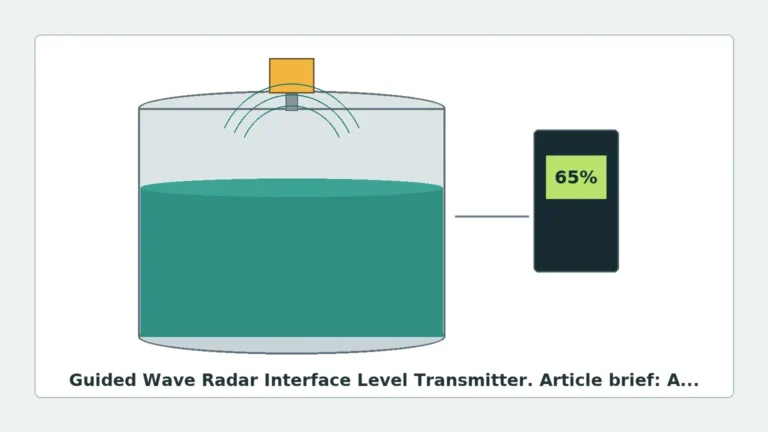
A: Yes, Guided Wave Radar (GWR) is particularly effective at interface measurement (e.g., oil over water). The signal reflects off the upper liquid (low dielectric) and continues through to reflect off the lower liquid (high dielectric).
Q: Does the tank material affect the radar probe?
A: For non-contact radar, a metal tank acts as a Faraday cage, which is ideal. Plastic tanks may allow signals to pass through, requiring a metal launch plate or a GWR probe to ensure signal integrity.
Q: How often does a radar probe require maintenance?
A: Because there are no moving parts, maintenance is minimal. Periodic inspection for material build-up or corrosion on the probe is recommended, especially in dirty or aggressive applications.
Q: What is the difference between 26GHz and 80GHz radar?
A: 80GHz radar has a much narrower beam angle, which allows it to avoid internal obstructions more easily and provides better resolution. However, 26GHz may be more robust in the presence of heavy dust or steam.
By carefully matching the radar level transmitter probe geometry and frequency to the specific process environment, industrial facilities can achieve high-precision level monitoring that remains stable over years of operation. For technical specifications and model comparisons, engineers should consult detailed product documentation on Radar Level Meters to ensure the selected instrument meets all safety and performance benchmarks.