Cpvc Flow Meters
Cpvc Flow Meters
In industrial fluid handling, the choice of piping material often dictates the choice of instrumentation. Chlorinated Polyvinyl Chloride (CPVC) is a widely utilized thermoplastic in chemical processing, water treatment, and metal finishing due to its superior resistance to corrosive reagents and its ability to withstand higher temperatures than standard PVC. Consequently, cpvc flow meters have become essential components for engineers tasked with monitoring flow rates in environments where metallic instruments would succumb to chemical attack.
This guide examines the technical principles, selection criteria, and installation requirements for flow measurement within CPVC piping systems. By understanding the mechanical and chemical limitations of the material alongside the physics of flow measurement, procurement and plant engineers can ensure long-term accuracy and system integrity.
Understanding CPVC in Flow Measurement Applications
CPVC is produced by the chlorination of polyvinyl chloride resin. This chemical modification increases the material’s glass transition temperature and enhances its fire resistance and mechanical strength. In the context of flow measurement, CPVC is preferred for its inertness to a broad spectrum of acids, bases, and salts.
Standard CPVC (often Schedule 80 for industrial use) can operate at temperatures up to 93°C (200°F), whereas standard PVC is typically limited to 60°C (140°F). However, the pressure rating of CPVC piping and the flow meters integrated into them decreases as the temperature rises. This "derating" factor is a critical consideration during the design phase of any flow monitoring system.
Core Measurement Principles for CPVC Systems
Flow meters used in CPVC systems generally fall into three categories: mechanical, ultrasonic, and electromagnetic. Each operates on a distinct physical principle, and the choice depends on fluid properties, required accuracy, and budget constraints.
Variable Area (Rotameters)
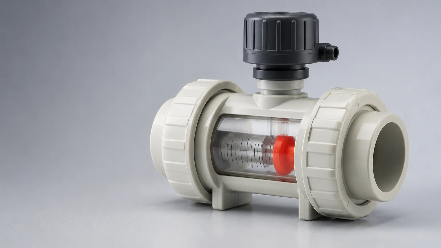
Variable area flow meters are among the most common cpvc flow meters used in industrial skids. The principle relies on a float inside a tapered CPVC or plastic tube. As fluid flows upward, the float rises until the upward force of the fluid (buoyancy and velocity pressure) equals the downward force of gravity. The position of the float against a graduated scale indicates the flow rate.
- Advantages: No external power required, visual indication, and high chemical resistance.
- Limitations: Limited to vertical installation with upward flow and generally lower accuracy (±2% to ±5% of full scale).
Ultrasonic (Transit-Time)
Ultrasonic flow meters are increasingly popular for CPVC applications because they can be "clamp-on" models. Transit-time ultrasonic meters use two transducers that act as both transmitters and receivers. They measure the time difference between an ultrasonic pulse traveling with the flow and one traveling against it. This time difference is directly proportional to the fluid velocity.
- Advantages: Non-invasive (no risk of leaks), zero pressure drop, and compatible with various pipe sizes.
- Limitations: Requires clean liquids with minimal entrained air or solids; higher initial cost.
Paddle Wheel and Turbine
These meters utilize a rotor or paddle wheel inserted into the flow stream. The fluid movement causes the wheel to spin at a rate proportional to the flow velocity. Magnets embedded in the paddle blades trigger a sensor (Hall Effect or inductive) to produce a frequency signal.
- Advantages: Compact design, digital output for integration with PLC systems, and relatively low cost.
- Limitations: Moving parts are subject to wear; requires filtration to prevent debris from jamming the paddle.
Key Selection Criteria and Evaluation Factors
When evaluating cpvc flow meters, engineers must look beyond the pipe size. The following factors are decisive in ensuring the meter performs within the specific process parameters.
Chemical Compatibility
While CPVC is highly resistant to many chemicals, it is susceptible to certain solvents, esters, and ketones. It is vital to verify the compatibility of the meter’s internal seals (often FKM or EPDM) and any wetted sensor elements (such as titanium or ceramic pins in paddle wheel meters) with the process fluid. For comprehensive system design, reviewing specialized instrumentation at the Main Page can provide insights into how different sensor materials interact with corrosive media.
Pressure and Temperature Ratings
As noted, CPVC’s mechanical strength is temperature-dependent. A meter rated for 10 bar (145 psi) at 23°C (73°F) may only be rated for 2.5 bar (36 psi) at 80°C (176°F). Engineers must consult the manufacturer’s derating charts to ensure the meter can handle the peak operating temperature and pressure of the system.
Flow Range and Turn-down Ratio
The turn-down ratio defines the range over which the meter can measure accurately. For example, a meter with a 10:1 turn-down ratio and a maximum flow of 100 L/min can accurately measure down to 10 L/min. Variable area meters typically have lower turn-down ratios compared to ultrasonic or electromagnetic options.
Technical Comparison and Selection Table
The following table provides a generalized comparison of common flow meter technologies utilized in CPVC piping environments.
| Feature | Variable Area (Rotameter) | Ultrasonic (Clamp-on) | Paddle Wheel | Electromagnetic (Insertion) |
| :— | :— | :— | :— | :— |
| Primary Wetted Material | CPVC / Borosilicate | N/A (Non-invasive) | CPVC / PVDF | CPVC / Hastelloy |
| Accuracy | ±2% to ±5% FS | ±0.5% to ±2% | ±1% to ±2% | ±1% |
| Installation Orientation | Vertical Only (Upward) | Any (Full Pipe) | Horizontal or Vertical | Horizontal or Vertical |
| Max Temperature | 93°C (200°F) | Pipe Dependent | 85°C – 90°C | 90°C |
| Maintenance | Low (Visual Check) | Very Low | Moderate (Moving Parts) | Low |
| Power Required | None | 24V DC / AC | 5V to 24V DC | 24V DC |
Installation Guidelines for CPVC Flow Meters
Proper installation is critical for the accuracy of any flow meter. Because CPVC is a rigid thermoplastic, specific mechanical considerations must be addressed during the piping layout.
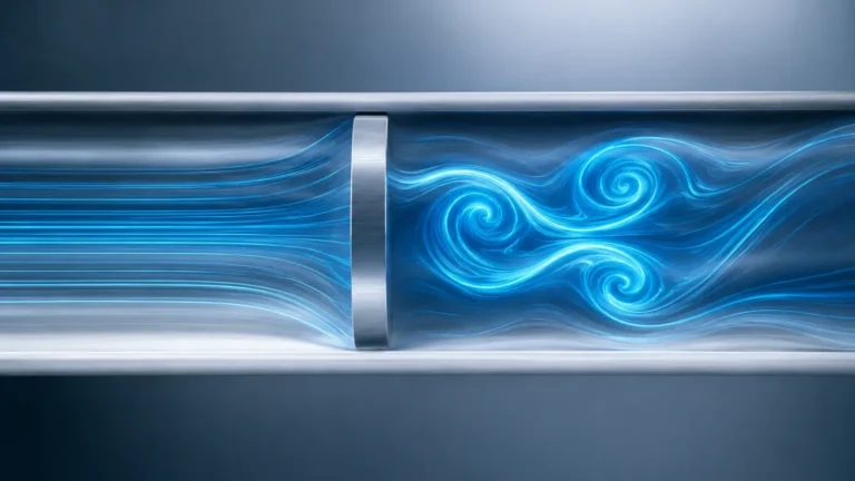
1. Straight Pipe Runs: Most cpvc flow meters require a specific length of straight pipe before (upstream) and after (downstream) the sensor to ensure a stable, laminar flow profile. A common rule is 10 pipe diameters (10D) upstream and 5 pipe diameters (5D) downstream. If a pump or a 90-degree elbow is immediately upstream, this requirement may increase to 20D or more.
2. Solvent Cement Curing: When installing CPVC flow meters with socket-weld connections, it is imperative to allow the solvent cement to cure fully according to the manufacturer's instructions before pressurizing the system. Failure to do so can lead to joint failure or the introduction of cement residue into the sensor mechanism.
3. Support and Alignment: CPVC piping can sag at elevated temperatures. Flow meters, especially heavier variable area models, should be independently supported to prevent stress on the piping joints. Ensure the meter is perfectly aligned to avoid "side-loading" on floats or paddles.
4. Air Elimination: Flow meters must remain full of liquid to provide accurate readings. In horizontal runs, avoid placing the meter at the highest point of the system where air pockets can collect. For ultrasonic meters, air bubbles can attenuate the signal, leading to "signal loss" errors.
Limitations and Operational Risks
While CPVC is a robust material, there are specific risks associated with its use in flow measurement:
- UV Degradation: Standard CPVC can become brittle when exposed to direct sunlight over long periods. If the flow meter is installed outdoors, it should be shielded or painted with a UV-resistant coating.
- Water Hammer: CPVC is susceptible to damage from hydraulic shock (water hammer). Quick-closing valves should be avoided near CPVC flow meters, or pulsation dampeners should be installed to protect the instrument.
- Particulate Matter: For mechanical meters like paddle wheels, suspended solids can cause abrasive wear or complete blockage. In such cases, a Y-strainer should be installed upstream, provided it does not interfere with the required straight pipe run.
- Thermal Expansion: CPVC has a higher coefficient of thermal expansion than metal. In long piping runs, expansion loops or offsets must be used to ensure that thermal growth does not exert mechanical force on the flow meter body.
Frequently Asked Questions (FAQs)
Q: Can I use a CPVC flow meter for compressed air or gases?
A: While some variable area meters are rated for gas, CPVC is generally not recommended for high-pressure compressed air or gas systems due to the risk of brittle failure. If a pipe fails under gas pressure, it can shatter, creating dangerous shrapnel. Always verify the manufacturer's safety rating for gas applications.
Q: How often should a CPVC paddle wheel meter be calibrated?
A: In clean water applications, annual calibration is usually sufficient. However, in corrosive chemical applications or those with slight particulates, semi-annual inspections are recommended to check for paddle wear or chemical scaling.
Q: Is Schedule 80 CPVC required for all flow meters?
A: Most industrial cpvc flow meters are designed for Schedule 80 dimensions because of the increased wall thickness and pressure rating. Using Schedule 40 piping with a Schedule 80 meter may require specific adapters and can create flow disturbances due to the difference in internal diameters (ID).
Q: Can ultrasonic meters work through CPVC pipe walls?
A: Yes, CPVC is an excellent conductor for ultrasonic signals. As long as the pipe is full and the transducers are properly coupled to the pipe surface with acoustic gel, transit-time ultrasonic meters provide highly accurate non-invasive measurement.
Conclusion
Selecting the right cpvc flow meters requires a balanced evaluation of chemical compatibility, thermal limits, and the physical properties of the fluid being measured. Whether opting for the simplicity of a rotameter or the advanced capabilities of a clamp-on ultrasonic sensor, adhering to strict installation standards—particularly regarding straight pipe runs and temperature derating—is essential for operational success. For professionals managing complex fluid systems, integrating reliable flow data with accurate level measurement is the cornerstone of process automation. Exploring the technical resources available on the Main Page can further assist in selecting the appropriate instrumentation for challenging industrial environments.