Vortex Flow Sensors
Vortex Flow Sensors
In the landscape of industrial process control, the accurate measurement of fluid flow is as critical as the monitoring of tank levels. Vortex flow sensors have emerged as a versatile and robust solution for measuring the flow rate of liquids, gases, and steam across a wide range of Reynolds numbers. Based on the principle of vortex shedding, these instruments offer a combination of high reliability, low maintenance, and wide turndown ratios, making them a staple in chemical, oil and gas, and water treatment applications.
Understanding the underlying physics and the specific application requirements is essential for engineers tasked with selecting the right instrumentation. This guide provides a comprehensive overview of vortex flow sensors, their operating principles, selection criteria, and installation best practices.
Measurement Principle: The Von Kármán Effect
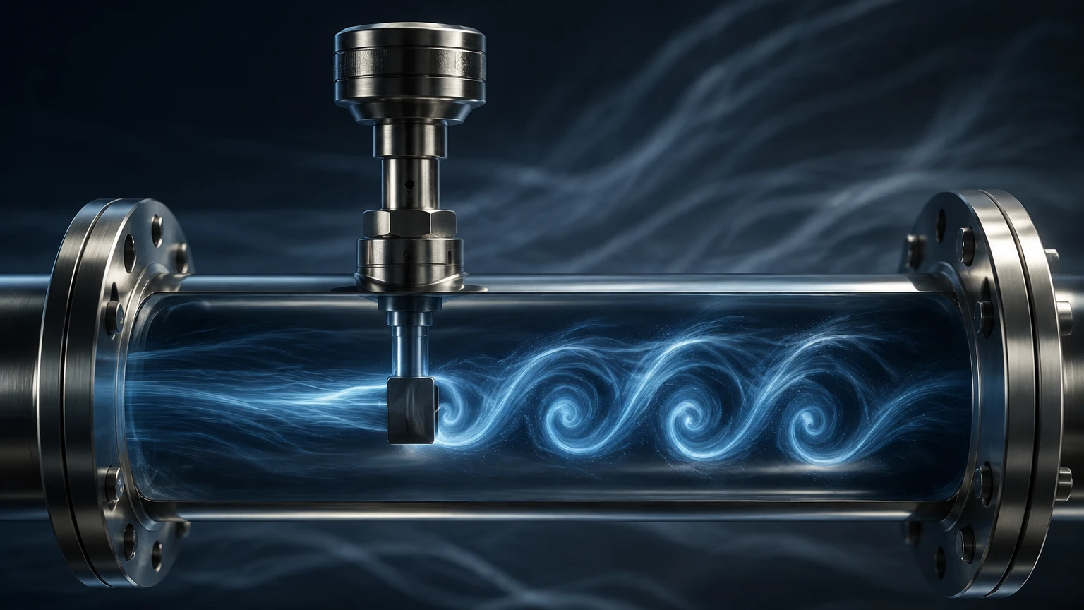
The operation of vortex flow sensors is based on a fluid dynamics phenomenon known as the von Kármán vortex street. When a fluid (liquid or gas) flows past a non-streamlined object, often referred to as a "bluff body" or "shedder bar," it cannot follow the sharp contours of the object. This causes the fluid to separate from the surface of the body, creating alternating areas of high and low pressure.
These pressure differentials result in the formation of vortices (swirls of fluid) that are shed alternately from each side of the bluff body. The frequency at which these vortices are shed is directly proportional to the velocity of the fluid moving through the pipe.
The Mathematical Relationship
The relationship between the shedding frequency and the flow velocity is expressed by the Strouhal number ($St$), a dimensionless parameter defined by the formula:
$$f = \frac{St \times V}{d}$$
Where:
* $f$ is the vortex shedding frequency (Hz).
* $St$ is the Strouhal number (a constant for a specific bluff body shape over a wide range of Reynolds numbers).
* $V$ is the velocity of the fluid (m/s).
* $d$ is the width of the bluff body (m).
Because the width of the shedder bar and the Strouhal number remain constant, the frequency of the vortices is a linear representation of the flow velocity. By multiplying the velocity by the cross-sectional area of the pipe, the sensor calculates the volumetric flow rate. In many modern industrial setups, these sensors are integrated into broader automation systems. For more information on integrated measurement solutions, you can visit the Main Page.
Key Components of a Vortex Flow Sensor
A standard vortex flow meter consists of three primary components:
1. The Meter Body: This is the mechanical housing that is installed directly into the pipeline. It contains the bluff body and must be constructed from materials compatible with the process fluid (e.g., 316 Stainless Steel or Hastelloy).
2. The Sensor Element: Usually located behind or inside the bluff body, the sensor detects the pressure fluctuations or ultrasonic signals caused by the vortices. Most industrial models use piezoelectric crystals that convert mechanical pressure pulses into electrical signals.
3. The Transmitter: The transmitter processes the raw signal from the sensor, filters out noise (such as pipe vibration), and converts the frequency into a standard industrial output, such as a 4-20mA signal, pulse output, or digital protocols like HART, Modbus, or Foundation Fieldbus.
Practical Selection Criteria
Choosing the correct vortex flow sensor requires a detailed analysis of the process conditions. Unlike some level measurement technologies that are non-contact, vortex sensors are in-line instruments and are thus subject to the physical and chemical properties of the media.
Fluid Phase and Properties
Vortex flow sensors are unique because they can measure liquids, dry gases, and both saturated and superheated steam. However, the fluid must be clean. Large solids or high concentrations of abrasive particles can damage the shedder bar or clog the sensor mechanism. Furthermore, the fluid must have a sufficiently high Reynolds number (typically $>10,000$ to $20,000$) to generate stable vortices.
Temperature and Pressure Limits
Standard vortex sensors can handle temperatures ranging from -40°C to +250°C, with specialized high-temperature models reaching up to +450°C. Pressure ratings depend on the flange or connection type, typically ranging from PN16 to PN100 (16 to 100 bar).
Selection Table: Typical Specifications
| Parameter | Standard Specification | High-Performance Specification |
| :— | :— | :— |
| Pipe Size Range | DN15 to DN300 (1/2" to 12") | Up to DN600 (24") with insertion types |
| Accuracy (Liquid) | ±0.75% to ±1.0% of rate | ±0.5% of rate |
| Accuracy (Gas/Steam) | ±1.0% to ±1.5% of rate | ±1.0% of rate |
| Repeatability | 0.2% | 0.1% |
| Turndown Ratio | 10:1 to 20:1 | Up to 30:1 |
| Max Temperature | 250°C (482°F) | 450°C (842°F) |
| Housing Material | 304/316 Stainless Steel | Hastelloy C / Carbon Steel |
Installation Considerations
The performance of vortex flow sensors is highly dependent on the flow profile. Turbulence or swirling flow caused by upstream valves, elbows, or pumps can introduce significant errors.
Straight Pipe Requirements
To ensure a fully developed and stable flow profile, manufacturers specify minimum straight pipe runs. A general rule of thumb is:
* Upstream: Minimum 10 to 20 times the nominal pipe diameter (D).
* Downstream: Minimum 5 times the nominal pipe diameter (D).
If the upstream piping includes multiple elbows in different planes or a pressure-reducing valve, the required upstream straight run may increase to 40D or more. If these distances cannot be met, flow straighteners or conditioners must be installed.
Orientation and Mounting
* Vertical Mounting: Ideal for liquid applications, provided the flow is upward. This ensures the pipe remains full and prevents air pockets from forming around the sensor.
* Horizontal Mounting: Common for steam and gas. For liquid flow in horizontal pipes, the sensor should be mounted so that the transmitter is either on top or on the side, depending on the fluid temperature, to protect the electronics from heat or condensation.
* Vibration: While modern transmitters use digital signal processing (DSP) to filter out noise, excessive pipe vibration can still interfere with the piezoelectric sensor. In such cases, the pipe should be supported or braced near the meter.
Limitations and Common Risks
While vortex flow sensors are highly versatile, they are not suitable for every application. Engineers should be aware of the following limitations:
1. Low Flow Cutoff: If the fluid velocity is too low, the pressure pulses generated by the vortices are too weak to be detected. This results in a "low flow cutoff" where the meter reads zero even if there is some movement in the pipe.
2. Cavitation: In liquid applications, if the pressure drops too low at the bluff body, the liquid may vaporize (cavitate). This creates significant noise, damages the sensor, and leads to inaccurate readings. Maintaining a backpressure of at least twice the pressure drop across the meter is recommended.
3. High Viscosity: As viscosity increases, the Reynolds number decreases. For highly viscous liquids (e.g., heavy oils), the vortex shedding may stop entirely or become non-linear, making the sensor ineffective.
4. Multi-phase Flow: Vortex sensors are designed for single-phase fluids. The presence of significant gas bubbles in a liquid, or liquid droplets in a gas (wet steam), will degrade accuracy.
Frequently Asked Questions (FAQ)
Q: Can vortex flow sensors measure mass flow?
A: Standard vortex sensors measure volumetric flow. However, "multivariable" vortex meters include integrated temperature and pressure sensors. By using these inputs and the known properties of the fluid (especially for steam and compressed air), the transmitter can calculate compensated mass flow in real-time.
Q: Do vortex flow sensors require periodic recalibration?
A: Because the shedding frequency depends on the geometry of the bluff body—which does not change over time unless there is significant erosion or buildup—vortex meters are very stable. They typically do not require the frequent recalibration associated with differential pressure or turbine meters.
Q: How do I handle applications with high pipe vibration?
A: First, ensure the meter is properly supported. Second, select a sensor with advanced Digital Signal Processing (DSP) and vibration compensation. Some sensors use dual-crystal designs to cancel out common-mode vibration noise while isolating the vortex signal.
Q: Is a vortex flow sensor suitable for hygienic food and beverage applications?
A: Generally, no. The bluff body creates a "dead zone" where bacteria can grow, and the meter body is difficult to clean-in-place (CIP) to the standards required for many food or pharmaceutical processes. Electromagnetic or Coriolis meters are usually preferred for these applications.
Conclusion
Vortex flow sensors provide a robust, cost-effective, and highly accurate means of measuring fluid flow in demanding industrial environments. By understanding the von Kármán effect and adhering to strict installation guidelines—particularly regarding straight pipe runs—operators can achieve reliable long-term performance with minimal maintenance. When integrated with advanced level measurement and control systems, these sensors form the backbone of efficient process automation. For further technical specifications and to explore a full range of industrial measurement instruments, consult the Main Page of our engineering resource.