Understanding Genesis Electrification
Understanding Genesis Electrification
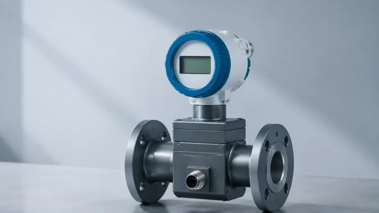
In the context of modern industrial automation, the transition from manual or mechanical monitoring to digital, electronic systems represents a critical phase often referred to as the genesis of electrification. For process industries, this shift is most visible in how liquid and solid levels are measured within tanks, silos, and open channels. Understanding genesis electrification requires a deep dive into the technologies that replace visual glass gauges and manual dipsticks with precise, electronic data streams that drive efficiency and safety.
Industrial level measurement has evolved from simple mechanical floats to sophisticated sensors using electromagnetic waves and pressure transducers. This article explores the fundamental principles of these electronic instruments, providing a technical framework for engineers and plant managers looking to modernize their facilities.
Principles of Electronic Level Measurement
Before implementing an electrification project, it is essential to understand the physics behind the primary measurement technologies. Electronic level meters generally fall into two categories: non-contact and contact-based measurement.
Radar Level Measurement (Non-Contact)
Radar level meters operate on the Time-of-Flight (ToF) principle. The sensor emits high-frequency electromagnetic pulses (typically in the GHz range) toward the surface of the medium. These pulses are reflected back to the sensor. The distance is calculated based on the time interval between transmission and reception.
There are two main types of radar technology used in industrial electrification:
1. Pulse Radar: Sends short bursts of energy and measures the transit time.
2. Frequency Modulated Continuous Wave (FMCW): Emits a continuous signal with a varying frequency. The difference in frequency between the transmitted and received signal is proportional to the distance.
Ultrasonic Level Measurement (Non-Contact)
Similar to radar, ultrasonic sensors use the ToF principle but utilize sound waves instead of electromagnetic pulses. The sensor emits an ultrasonic pulse (usually between 20 kHz and 200 kHz). The pulse travels through the air, hits the liquid surface, and returns. Because the speed of sound is affected by air temperature, these sensors must include temperature compensation to maintain accuracy.
Hydrostatic Level Measurement (Contact)
Hydrostatic transmitters measure the pressure exerted by a liquid column at a specific point. According to the laws of fluid mechanics, the pressure at the bottom of a tank is directly proportional to the height of the liquid and its density. The formula used is $P = \rho \cdot g \cdot h$, where $P$ is pressure, $\rho$ is density, $g$ is gravity, and $h$ is the height of the liquid. Electrification here involves converting this mechanical pressure into a 4-20mA or digital signal.
Magnetic Level Gauges with Transmitters
Magnetic level gauges utilize a float containing a permanent magnet that moves with the liquid level inside a bypass chamber. While the primary display is mechanical (flipping flags), electrification is achieved by mounting a magnetostrictive or reed-switch-based transmitter to the outside of the chamber. The float's magnetic field triggers the electronic sensor, providing a continuous remote signal.
The Role of Data in Genesis Electrification
Understanding genesis electrification is not merely about replacing a mechanical tool with an electronic one; it is about the integration of data into the broader industrial ecosystem. When a facility undergoes this transition, the primary goal is to move from "periodic observation" to "continuous monitoring."
Electronic level sensors provide real-time data that can be fed into Programmable Logic Controllers (PLCs) or Distributed Control Systems (DCS). This allows for:
* Automated Pump Control: Preventing dry runs or overflows by setting high and low-level alarms.
* Inventory Management: Accurate tracking of raw materials and finished products in real-time.
* Safety Interlocks: Ensuring that hazardous chemicals are contained within safe limits through redundant electronic monitoring.
Selection Criteria for Electronic Level Meters
Choosing the right instrument is the most critical step in the electrification process. Engineers must evaluate several factors to ensure long-term reliability.
1. Media Properties
The physical and chemical characteristics of the substance being measured dictate the technology choice. For instance, high-dielectric liquids are ideal for radar, while heavy foam can absorb ultrasonic signals, leading to measurement errors. In applications involving corrosive chemicals, non-contact sensors or those made from specialized materials like PTFE (Polytetrafluoroethylene) are required.
2. Process Conditions
* Temperature: High temperatures can affect the speed of sound (ultrasonic) or the electronics of a sensor. Radar is generally more stable across wide temperature ranges.
* Pressure: Vacuum or high-pressure environments require sensors with robust seals and specific pressure ratings.
* Turbulence: Agitators or splashing can cause signal scattering for non-contact sensors. In such cases, a stilling well or a guided wave radar may be necessary.
* Vapor and Dust: Heavy dust in silos can block ultrasonic signals, whereas radar pulses can typically penetrate dust and steam.
3. Measuring Range
The height of the vessel determines the required power of the sensor. Ultrasonic sensors are often limited to ranges under 20 meters (approx. 65 feet), while high-frequency radar can measure up to 70 meters (approx. 230 feet) or more.
Technical Selection Table
| Technology | Measurement Type | Accuracy | Max Range (Typical) | Ideal For | Limitations |
| :— | :— | :— | :— | :— | :— |
| Radar | Non-contact | ±1 mm to ±5 mm | 70 m (230 ft) | Hydrocarbons, solids, corrosive media | High initial cost |
| Ultrasonic | Non-contact | ±0.25% of range | 15 m (50 ft) | Water, wastewater, simple liquids | Affected by foam, steam, and wind |
| Hydrostatic | Contact | ±0.1% to ±0.5% | 200 m (650 ft) | Open tanks, deep wells, vented vessels | Sensitive to density changes |
| Magnetic | Contact | ±5 mm to ±10 mm | 6 m (20 ft) | High pressure, high temperature, toxic liquids | Limited to liquids; requires bypass chamber |

Installation Considerations and Best Practices
Successful electrification depends heavily on proper installation. Even the most advanced sensor will fail if placed incorrectly.
* Avoid the "Dead Zone": Every electronic level meter has a "blocking distance" or dead zone near the sensor face where measurement is impossible. Ensure the sensor is mounted high enough that the maximum liquid level never enters this zone.
* Nozzle Geometry: For radar and ultrasonic sensors, the mounting nozzle should be short and wide enough to prevent the signal from reflecting off the nozzle walls (ringing).
* Internal Obstructions: Avoid mounting sensors directly above ladders, heating coils, or inflow pipes. These obstructions create false echoes that can confuse the electronic signal processing.
* Alignment: Non-contact sensors must be mounted perpendicular to the liquid surface to ensure the maximum signal return. For solids, an aiming flange may be required to account for the angle of repose.
* Grounding and Shielding: Electronic sensors are susceptible to Electromagnetic Interference (EMI). Use shielded cables and ensure proper grounding to prevent signal noise from VFDs (Variable Frequency Drives) or other heavy machinery.
Limitations and Common Risks
While electrification offers numerous benefits, it is not without challenges. Understanding these limitations is part of a comprehensive strategy.
1. Power Supply Dependency: Unlike a mechanical sight glass, electronic sensors require a stable power supply (typically 24V DC). Power surges or outages can lead to data loss unless backup systems are in place.
2. Signal Interference: In complex tank geometries, multi-path reflections can occur. Modern sensors use "False Echo Suppression" software to ignore these static reflections, but initial commissioning requires technical expertise.
3. Media Buildup: For contact sensors like hydrostatic transmitters, buildup of sludge or crystals on the diaphragm can cause drift. Regular cleaning or the use of flush-diaphragm designs is necessary.
4. Dielectric Constant (Dk): Radar relies on the difference in Dk between the air and the medium. If the Dk is too low (e.g., certain liquefied gases), the signal may pass through the liquid rather than reflecting off it.
Conclusion and Next Steps
Understanding genesis electrification is the first step toward a fully automated and data-driven industrial operation. By moving away from manual measurement and embracing electronic level sensing, facilities can achieve higher accuracy, improved safety, and better resource management. Whether you are dealing with water treatment, chemical processing, or oil and gas storage, the transition to electronic monitoring is a foundational requirement for modern engineering.
When evaluating your specific application, it is helpful to Review product options and application support to ensure the selected hardware aligns with your process requirements. Professional consultation during the selection phase can prevent costly installation errors and ensure the longevity of your instrumentation.
Frequently Asked Questions (FAQ)
Q: Can electronic level meters work in hazardous areas?
A: Yes, most industrial level meters are available with ATEX, IECEx, or UL certifications for use in explosive atmospheres. These typically use "Intrinsically Safe" (Ex i) or "Explosion-Proof" (Ex d) protection methods.
Q: How often do electronic level sensors need calibration?
A: This depends on the technology and the application. Hydrostatic sensors may require annual calibration due to sensor drift, while radar sensors are generally more stable and may only need a functional check every 2-3 years.
Q: Is radar better than ultrasonic?
A: Radar is generally more versatile because it is not affected by air temperature, pressure, or vapors. However, ultrasonic sensors are often more cost-effective for simple water-based applications in ambient conditions.
Q: What is a 4-20mA signal?
A: It is a standard analog signaling method where 4mA represents the 0% level (empty) and 20mA represents the 100% level (full). This is the most common way to integrate level sensors into industrial control systems.