Definition of Electrification
Definition of Electrification
In the modern industrial landscape, the definition of electrification extends far beyond the simple provision of power to a building or a machine. In a B2B and process engineering context, electrification refers to the systematic transition from manual, mechanical, or thermal-based systems to those powered by electricity, specifically focusing on the integration of electronic controls, sensors, and automated data transmission. For industries such as water treatment, chemical processing, and oil and gas, electrification is the fundamental precursor to Industry 4.0, enabling the digital monitoring and control of critical assets.
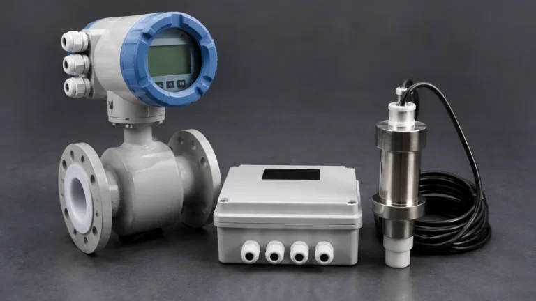
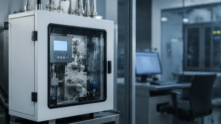
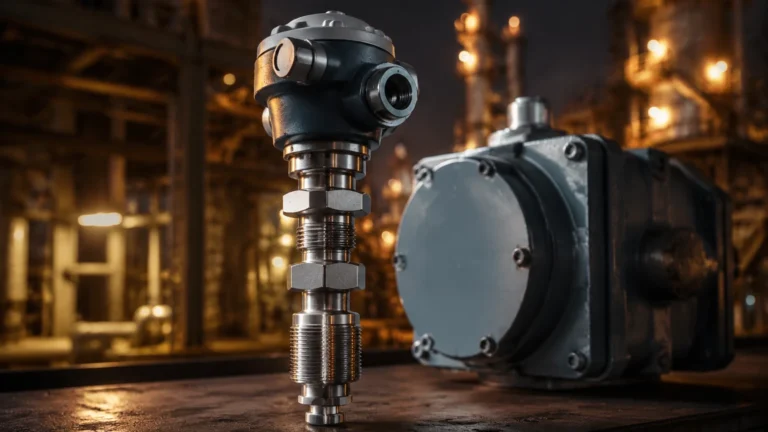
At its core, the industrial definition of electrification involves the replacement of pneumatic or purely mechanical actuators and indicators with electronic equivalents. This shift allows for higher precision, remote accessibility, and the ability to aggregate data for predictive maintenance. Within the niche of level measurement, this transition is particularly visible. Where operators once relied on manual dipsticks or simple sight glasses, they now utilize advanced radar and ultrasonic transmitters that convert physical levels into standardized electrical signals.
As a professional manufacturer of industrial level measurement instruments, Welk provides the hardware necessary to facilitate this transition. By understanding the technical nuances of electrification, engineers can better select instruments that not only measure accurately but also integrate seamlessly into a broader electrified grid. To explore the full range of electronic measurement solutions, professionals can visit the Main Page for detailed product specifications.
The Core Principles of Industrial Electrification
To apply the definition of electrification to a process plant, one must understand the three pillars of the transition: power conversion, signal transmission, and data integration.
1. Power Conversion: This involves taking a physical property—such as the pressure exerted by a liquid column or the time it takes for a sound wave to travel—and converting it into an electrical charge or pulse.
2. Signal Standardization: Once a physical property is converted to electricity, it must be standardized. The most common standard in industrial electrification is the 4-20mA loop, where 4mA represents the minimum value (0%) and 20mA represents the maximum (100%).
3. Digital Superimposition: Modern electrification often involves "Smart" protocols like HART (Highway Addressable Remote Transducer), which superimposes a digital signal on top of the analog 4-20mA current. This allows the instrument to communicate diagnostic data alongside the primary measurement.
By moving away from mechanical systems, plants reduce the need for physical presence at the measurement site, significantly increasing safety in hazardous or hard-to-reach environments.
Electrification in Level Measurement: From Mechanical to Electronic
The evolution of level measurement provides a clear practical example of electrification in action. Historically, level monitoring was a labor-intensive task.
The Mechanical Era
Before the widespread electrification of sensors, plants used mechanical floats connected to external pointers or sight glasses (transparent tubes attached to the side of a vessel). While reliable, these systems offered no way to transmit data to a central control room without manual observation. They were also prone to leaks and required frequent cleaning.
The Electronic Transition
The introduction of hydrostatic pressure transmitters and ultrasonic sensors marked the first major wave of electrification. These devices replaced the human eye with a transducer. A transducer is an electronic component that converts one form of energy (pressure or sound) into an electrical signal. This allowed for the first time the continuous, remote monitoring of tank levels from a centralized PLC (Programmable Logic Controller).
Measurement Principles of Electrified Level Sensors
Before selecting a device for an electrified system, it is essential to understand the underlying measurement principles. Different technologies interact with the electrical grid and the process media in unique ways.
Radar Level Measurement (FMCW and Pulse)
Radar sensors represent the pinnacle of electrified level measurement. They emit high-frequency electromagnetic waves (typically in the 26GHz or 80GHz range).
* Principle: The sensor measures the "Time of Flight" (ToF)—the time it takes for the pulse to travel to the surface of the material and back.
* Electrification Advantage: Because radar uses electromagnetic waves, it is unaffected by air temperature, vacuum, or pressure changes, providing a highly stable digital output.
Ultrasonic Level Measurement
Ultrasonic sensors use piezoelectric crystals to generate mechanical sound waves.
* Principle: The crystal vibrates when an electrical voltage is applied, sending a sound pulse. The time taken for the echo to return is converted into a distance measurement.
* Electrification Advantage: These are cost-effective, non-contact solutions ideal for water and wastewater applications where the media might be corrosive to submerged sensors.
Hydrostatic Level Measurement
This method relies on the relationship between the height of a liquid and the pressure it exerts at the base of a vessel.
* Principle: A pressure diaphragm senses the weight of the liquid column. An internal strain gauge or capacitive cell converts this physical pressure into a change in electrical resistance or capacitance, which is then processed into a 4-20mA signal.
* Electrification Advantage: Highly accurate for deep wells and vented tanks where non-contact sensors might struggle with internal obstructions.
Selection Criteria for Electronic Level Transmitters
Choosing the right instrument within an electrified framework requires a comparison of technical specifications. The following table outlines the key considerations for the most common electrified level technologies.
| Feature | Radar (Non-Contact) | Ultrasonic | Hydrostatic | Magnetic Level Gauge (with Transmitter) |
| :— | :— | :— | :— | :— |
| Measurement Range | Up to 120m | 0.3m to 30m | 1m to 200m | 0.5m to 6m |
| Accuracy | ±1mm to ±5mm | ±0.25% of range | ±0.1% to ±0.5% | ±5mm |
| Power Supply | 24V DC (2-wire) | 24V DC / 220V AC | 12-36V DC | 24V DC |
| Output Signal | 4-20mA, HART, Modbus | 4-20mA, Relay | 4-20mA, RS485 | 4-20mA, HART |
| Process Temp. | -40°C to +250°C | -40°C to +80°C | -20°C to +80°C | -40°C to +400°C |
| Media Influence | Unaffected by density | Affected by foam/vapor | Affected by density | Affected by density |

Installation Considerations for Electrified Instruments
Proper installation is critical to ensure that the definition of electrification translates into operational efficiency. Electronic instruments are sensitive to environmental and electrical interference.
Wiring and Shielding
To prevent electromagnetic interference (EMI) from high-power equipment like motors or variable frequency drives (VFDs), signal cables must be shielded. The shield should typically be grounded at only one end (usually the control room end) to prevent ground loops, which can introduce noise into the measurement signal.
Power Supply Stability
Most industrial level meters operate on a 24V DC loop. It is vital to ensure that the power supply is regulated and capable of handling the inrush current of multiple devices. In large-scale electrification projects, redundant power supplies are recommended to prevent total system failure during a power glitch.
Mounting and Dead Zones
Every electronic level sensor has a "dead zone" or "blocking distance" (typically 0.1m to 0.5m). This is the area directly beneath the sensor where measurement is impossible due to the time required for the electronics to switch from transmitting to receiving. For electrified systems, the sensor must be mounted high enough to ensure the maximum liquid level never enters this zone.
Limitations and Challenges of Electrification
While the definition of electrification implies progress, it also introduces specific technical challenges that engineers must mitigate:
* Signal Attenuation: In ultrasonic systems, heavy foam or dust can absorb the sound waves, leading to a "loss of echo." In these cases, switching to a high-frequency radar is often necessary.
* Hazardous Areas: Electrified instruments in chemical or oil and gas plants must be explosion-proof. This requires the use of Intrinsic Safety (IS) barriers or Flameproof (Ex d) enclosures to ensure that the electrical energy in the circuit cannot ignite a volatile atmosphere.
* Power Dependency: Unlike a simple mechanical float, an electrified sensor requires constant power. In remote locations, this may necessitate the installation of solar panels and battery storage systems.
Frequently Asked Questions (FAQs)
Q: What is the difference between a level switch and a level transmitter in an electrified system?
A: A level switch is a point-level detection device that provides a simple binary output (on/off) when a specific level is reached. A level transmitter provides continuous measurement, outputting a variable signal (like 4-20mA) that corresponds to the exact level at any given time.
Q: Can I electrify an existing mechanical tank gauge?
A: Yes. Many mechanical systems, such as magnetic level gauges, can be retrofitted with reed-chain transmitters or magnetostrictive sensors. These sensors move along the outside of the gauge and convert the position of the internal float into an electrical signal without breaking the pressure boundary of the tank.
Q: How does the definition of electrification relate to the "Internet of Things" (IoT)?
A: Electrification is the physical layer of IoT. By converting physical levels into electrical data, instruments can then be connected to gateways that send information to the cloud, allowing for global asset monitoring and advanced data analytics.
Q: Why is 4-20mA the standard for electrified sensors?
A: The 4-20mA standard is used because it is highly resistant to electrical noise over long distances. Furthermore, the "live zero" (4mA) allows the system to distinguish between a zero-level reading and a broken wire (0mA).
Conclusion
Understanding the definition of electrification is essential for any process engineer looking to modernize their operations. By transitioning from mechanical to electronic level measurement, facilities gain the accuracy, safety, and data integration required for competitive industrial performance. Whether implementing radar, ultrasonic, or hydrostatic solutions, the goal remains the same: transforming physical reality into actionable electrical data. For those beginning this transition or seeking to optimize existing electrified systems, Welk offers a comprehensive portfolio of instruments designed for reliability in the most demanding environments. Detailed technical documentation and product selection guides are available on our Main Page.