Electronic Drilling Recorder
Electronic Drilling Recorder
In the modern oil and gas industry, the Electronic Drilling Recorder (EDR) has evolved from a simple data logging tool into a comprehensive mission-control system for drilling operations. At its core, an EDR is a centralized data acquisition platform that monitors, records, and displays real-time parameters from various sensors distributed across a drilling rig. While the system tracks mechanical variables like weight on bit (WOB), torque, and revolutions per minute (RPM), one of its most critical functions is the precise monitoring of fluid levels within the mud pits and storage tanks.
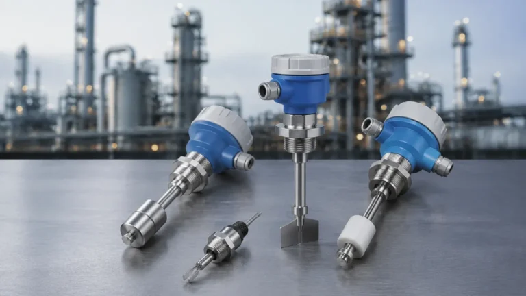
For engineers and rig managers, the reliability of an EDR depends entirely on the accuracy of the instrumentation feeding it. As a professional manufacturer, Welk provides the high-precision level measurement instruments—including radar level meters and ultrasonic sensors—that serve as the "eyes" of the electronic drilling recorder. This guide explores the technical integration of level measurement technologies within EDR systems, offering practical selection criteria and installation best practices.
Understanding the Electronic Drilling Recorder System
An electronic drilling recorder replaces the traditional mechanical "Geolograph" by digitizing rig data. It facilitates real-time decision-making by providing a synchronized view of the drilling process to both the driller on-site and remote engineering teams. The system typically consists of a central processing unit, ruggedized touch-screen displays (HMI), and a network of industrial sensors.
In the context of fluid management, the EDR performs "Pit Volume Totalizing" (PVT). This involves aggregating data from multiple level sensors installed on active mud tanks, reserve pits, and trip tanks. By monitoring the total volume of drilling fluid, the EDR can detect a "kick" (an influx of formation fluid into the wellbore) or a "lost circulation" event (drilling fluid escaping into the formation). Both scenarios are high-risk; early detection via precise level measurement is the primary defense against well control incidents.
Critical Level Measurement Technologies for EDR Integration
To provide the EDR with reliable data, several measurement principles are employed depending on the fluid properties and environmental conditions. Understanding these principles is essential before selecting hardware from the Main Page.
Radar Level Measurement (Time of Flight)
Radar level meters, particularly those operating at high frequencies like 80GHz, are the gold standard for EDR integration. These sensors emit a high-frequency electromagnetic pulse that travels to the surface of the mud and reflects back. The sensor calculates the distance based on the time of flight (ToF).
* Advantages: Radar is unaffected by air temperature, pressure, or the presence of vapors and dust. The narrow beam angle of 80GHz models allows for installation in narrow tanks with internal obstructions like agitators.
* Application: Ideal for active mud pits where steam, chemical vapors, and heavy agitation are common.
Ultrasonic Level Sensors
Ultrasonic sensors use sound waves to measure distance. The sensor emits an ultrasonic pulse that reflects off the liquid surface.
* Advantages: Non-contact and cost-effective. These are excellent for water storage tanks or chemical additives where the environment is relatively stable.
* Limitations: Sound velocity changes with air temperature and gas composition. While modern sensors include temperature compensation, they may struggle in pits with heavy foam or dense vapors that absorb sound waves.
Hydrostatic Level Transmitters
These sensors measure the pressure exerted by the liquid column. Since pressure is proportional to the height of the liquid and its density, the EDR can calculate the level.
* Advantages: Highly accurate for deep tanks and unaffected by surface foam or turbulence.
* Limitations: They are contact-based and can be prone to clogging if the drilling mud has a high solids content or if the fluid density changes frequently without recalibration in the EDR software.
Application Selection: Choosing the Right Sensor for Drilling Fluids
Selecting the appropriate sensor for an electronic drilling recorder requires an analysis of the specific tank environment. The following table provides a comparison based on typical drilling rig requirements.
| Feature | 80GHz Radar Level Meter | Ultrasonic Level Sensor | Hydrostatic Transmitter |
| :— | :— | :— | :— |
| Measurement Range | Up to 120m (393 ft) | Up to 15m (49 ft) | Dependent on probe length |
| Accuracy | ±1mm to ±2mm | ±0.25% of range | ±0.1% to ±0.5% of span |
| Surface Turbulence | High resistance | Moderate resistance | Excellent resistance |
| Foam Influence | Minimal (frequency dependent) | High (may lose signal) | None |
| Vapor/Steam | No effect | Significant effect | No effect |
| Maintenance | Low (non-contact) | Low (non-contact) | Moderate (contact-based) |
For most EDR applications involving drilling mud, non-contact radar is recommended due to its immunity to the changing dielectric constants and densities of the fluid, as well as its ability to penetrate heavy steam or dust.
Installation and Maintenance Guidelines for Drilling Environments
Proper installation is paramount to ensuring the electronic drilling recorder receives clean, noise-free data. Rig environments are notoriously harsh, characterized by vibration, mechanical impact, and corrosive chemicals.
1. Mounting and Positioning
The sensor should be mounted perpendicular to the liquid surface. For radar and ultrasonic sensors, avoid placing the unit too close to the tank wall to prevent false reflections (side-lobe interference). A minimum distance of 200mm (approx. 8 inches) from the wall is generally recommended for tanks under 5 meters (16.4 ft) in height.
2. Avoiding Obstructions
Drilling pits often contain agitators, ladders, and suction pipes. When integrating with an EDR, use sensors with narrow beam angles (e.g., 3° to 6°) to "steer" the signal around these obstacles. If obstructions are unavoidable, the EDR or the sensor itself must support "false echo suppression" to ignore static reflections.
3. Environmental Protection
Sensors on a drilling rig must be rugged. Welk recommends using instruments with at least IP67 or IP68 ingress protection ratings. Furthermore, because drilling fluids can be oil-based or contain volatile chemicals, sensors must be certified for hazardous areas (Ex d or Ex ia) to comply with international safety standards.
4. Signal Integration
Most EDR systems accept 4-20mA analog signals or digital protocols like Modbus RTU or HART. Ensure the cabling is shielded to prevent electromagnetic interference (EMI) from large rig motors and top drives from corrupting the level data.

Operational Challenges and Risk Mitigation
While an electronic drilling recorder significantly enhances safety, users must be aware of potential risks and limitations to maintain system integrity.
* Signal Loss due to Heavy Foam: In certain drilling conditions, the mud may foam excessively. This can absorb ultrasonic signals or scatter radar pulses. In these cases, using a stilling well (a vertical pipe that stabilizes the surface) can provide a clear measurement path for the sensor.
* Build-up on Sensor Face: Mud splash can dry on the sensor face, potentially causing a loss of signal. While many Welk radar sensors feature a flat-face design that resists build-up, regular visual inspections are necessary during rig moves or maintenance intervals.
* Data Latency: In high-speed drilling, even a few seconds of delay in level reporting can be critical. Ensure the EDR's sampling rate is synchronized with the sensor's response time to provide a truly real-time view of pit volumes.
Frequently Asked Questions
Q: Can one EDR handle different types of level sensors simultaneously?
A: Yes. Most modern EDR systems are sensor-agnostic. You can use radar for the active mud pits and hydrostatic transmitters for the fuel storage tanks, with all data aggregated into a single dashboard.
Q: How does mud density affect level measurement?
A: For radar and ultrasonic (non-contact) sensors, density has no effect on the level measurement. However, for hydrostatic transmitters, a change in mud weight (e.g., from 9.0 ppg to 12.0 ppg) will change the pressure reading. The EDR software must be updated with the current mud weight to calculate the correct level when using hydrostatic methods.
Q: Is it necessary to recalibrate sensors when changing drilling fluid types?
A: If using radar or ultrasonic technology, recalibration is generally not required when switching between water-based mud (WBM) and oil-based mud (OBM). If using hydrostatic sensors, recalibration or software adjustment is mandatory due to the density change.
Conclusion
The electronic drilling recorder is only as effective as the data it receives. By selecting robust, high-precision level measurement instruments, operators can ensure their EDR provides the accurate volume tracking necessary for safe and efficient drilling. Whether you require the advanced precision of 80GHz radar or the rugged reliability of hydrostatic transmitters, choosing the right technology for the specific rig environment is a critical engineering decision. For detailed product specifications and application support, professionals should consult the Main Page to review available measurement solutions.