Vector Controls Inc
Vector Controls Inc
In the landscape of industrial automation and process management, the integration of precise sensing technology with robust control logic is fundamental to operational efficiency. While manufacturers like Welk provide the primary hardware for level measurement—such as radar, ultrasonic, and hydrostatic transmitters—the broader ecosystem includes control solution providers like Vector Controls Inc. Understanding how these components interface is critical for engineers designing systems for water treatment, chemical processing, and oil and gas applications.
Industrial level control is rarely a standalone function. It requires a synergy between the sensor (the "eyes" of the system) and the controller (the "brain"). This article explores the technical principles of level measurement, the selection criteria for integrated control systems, and the practical considerations for implementing these technologies in demanding environments.
Principles of Level Measurement Technology
Before selecting a control interface or a specific product from a provider like Vector Controls Inc, it is essential to understand the physics behind the measurement. Industrial level instruments generally fall into two categories: non-contact and contact-based measurement.
Radar Level Measurement (ToF)
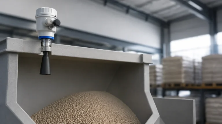
Radar level meters operate on the Time-of-Flight (ToF) principle. The device emits a high-frequency microwave signal (typically in the 26GHz or 80GHz range) toward the material surface. The signal reflects off the media and returns to the sensor. By measuring the time interval between emission and reception, the instrument calculates the distance to the surface.
* 80GHz Radar: Offers a narrow beam angle, making it ideal for vessels with internal obstructions or narrow nozzles. It provides high precision even in dusty or steaming environments.
* 26GHz Radar: A versatile choice for standard liquid storage, offering a balance between cost and performance.
Ultrasonic Level Sensing
Ultrasonic sensors utilize sound waves rather than electromagnetic waves. A piezoelectric crystal within the sensor converts electrical energy into mechanical pulses. These pulses travel through the air, bounce off the target, and return. Because the speed of sound is affected by air temperature, these sensors usually include integrated temperature compensation.
Hydrostatic Pressure Measurement
This method relies on the principle that the pressure at the bottom of a liquid column is directly proportional to the height of that column and the density of the liquid. A hydrostatic transmitter, often submerged or mounted at the tank bottom, measures this pressure and converts it into a level reading. This is a reliable, cost-effective solution for vented tanks where liquid density remains constant.
Magnetic Level Gauges
For high-pressure or high-temperature applications where electronic components must be isolated from the process media, magnetic level gauges provide a mechanical solution. A float containing a permanent magnet moves with the liquid level inside a bypass chamber. This magnet actuates a series of external flags or a continuous transmitter, providing both local visual indication and an electronic signal for the control system.
Integrating Sensors with Control Systems
Systems provided by entities like Vector Controls Inc often focus on the control and communication layer. In a typical B2B industrial setup, a Welk level transmitter sends a signal—most commonly a 4-20mA analog loop, often with HART protocol, or a digital signal like Modbus RS485—to a universal controller or a PLC (Programmable Logic Controller).
The Role of the Controller
The controller interprets the signal from the level meter to perform specific actions:
1. Pump Control: Starting or stopping pumps to maintain a specific level range (Lead/Lag control).
2. Alarm Management: Triggering high-level or low-level alerts to prevent overflows or dry-running of pumps.
3. Data Logging: Recording level trends for regulatory compliance, especially in water treatment and chemical storage.
4. PID Control: Maintaining a precise level by modulating a control valve, essential in continuous flow processes.
Technical Selection Criteria
Choosing the right combination of level sensing and control hardware requires an analysis of the process media and the physical environment. The following table provides a comparison of technologies based on common industrial variables.
Technology Selection Table
| Feature | Radar (Non-contact) | Ultrasonic | Hydrostatic | Magnetic Gauge |
| :— | :— | :— | :— | :— |
| Media Type | Liquids, Solids, Slurries | Liquids, Some Solids | Clean Liquids | Liquids |
| Accuracy | ±1mm to ±5mm | ±0.25% of range | ±0.1% to ±0.5% | ±5mm to ±10mm |
| Pressure Range | Up to 40 bar+ | Atmospheric | Up to 20 bar | Up to 100 bar+ |
| Temperature | Up to 250°C+ | -40°C to 80°C | -10°C to 80°C | Up to 400°C |
| Foam Handling | Excellent (80GHz) | Poor | Good | Excellent |
| Cost Profile | Higher | Moderate | Low to Moderate | Moderate to High |
When evaluating options, engineers should consult the Main Page of the manufacturer's catalog to ensure the selected instrument matches the chemical compatibility and pressure ratings of the application.
Installation and Engineering Considerations
Correct installation is as vital as instrument selection. Even the most advanced controller from Vector Controls Inc cannot compensate for poor signal quality resulting from incorrect sensor placement.
Mounting Position
* Dead Zones: Every non-contact sensor has a "blocking distance" or dead zone near the sensor face where measurement is impossible. Ensure the maximum liquid level does not enter this zone.
* Obstructions: Avoid mounting sensors directly above ladders, agitators, or inflow pipes. For radar, internal structures can cause "ghost echoes," though modern software can often map these out.
* Nozzle Geometry: For ultrasonic and radar sensors, the nozzle height and diameter must allow the signal beam to spread without hitting the nozzle walls.
Cabling and Signal Integrity
In industrial environments, Electromagnetic Interference (EMI) can degrade the 4-20mA signal. Use shielded twisted-pair cabling and ensure proper grounding at the controller end. If the distance between the sensor and the control room is significant, consider using digital communication protocols like Modbus, which are more resilient to noise.

Limitations and Challenges
No single technology is a universal solution. Understanding limitations prevents system failure:
* Ultrasonic Limitations: These sensors fail in vacuum conditions because sound waves require a medium (air) to travel. They are also sensitive to heavy foam, which absorbs the sound pulse.
* Radar Limitations: While highly versatile, radar signals can be affected by media with a very low dielectric constant (e.g., certain oils or liquefied gases), which may require a guided wave radar (GWR) approach.
* Hydrostatic Limitations: Changes in liquid density (due to temperature fluctuations or mixing of different chemicals) will directly result in measurement errors unless the system is compensated.
Practical Application: Water Treatment
In a typical water treatment facility, ultrasonic sensors are often used for open channel flow and tank level measurement due to their cost-effectiveness. These sensors feed data into a central control panel. If the application involves chemical dosing (such as sodium hypochlorite), radar is preferred due to the corrosive nature of the vapors, which can degrade the face of an ultrasonic transducer over time.
For those seeking specific hardware configurations, it is advisable to Review product options and application support to determine which sensor type best integrates with existing PLC or Vector Controls Inc infrastructure.
Frequently Asked Questions (FAQs)
Q: Can I use a standard level controller with any level transmitter?
A: Generally, yes, provided the signal types match. Most industrial controllers accept a standard 4-20mA DC signal. However, if you require advanced diagnostics, both the sensor and the controller must support protocols like HART or Profibus.
Q: How does foam affect level measurement?
A: Foam density determines the impact. Light, airy foam may be transparent to radar but will block ultrasonic waves. Dense, thick foam can reflect radar signals prematurely. In such cases, a magnetic level gauge or a displacement-type sensor may be more reliable.
Q: What is the maintenance requirement for these systems?
A: Non-contact sensors (radar and ultrasonic) are virtually maintenance-free as they have no moving parts. Hydrostatic sensors may require periodic cleaning of the diaphragm if the liquid is prone to scaling or buildup. Magnetic gauges should be flushed periodically to prevent sediment from trapping the float.
Q: Is it possible to measure level in a pressurized tank?
A: Yes. Radar and magnetic level gauges are excellent for pressurized vessels. Hydrostatic sensors can also be used, but they require a differential pressure (DP) setup to subtract the overhead gas pressure from the total pressure at the bottom.
By carefully aligning the measurement principle with the specific demands of the process and ensuring seamless integration with control logic, operators can achieve high levels of reliability and safety in their industrial automation projects.