Hydrostatic Sensor
Hydrostatic Sensor
In the field of industrial process control, the hydrostatic sensor remains one of the most reliable and widely adopted technologies for continuous level measurement. By leveraging the fundamental laws of physics—specifically the relationship between liquid height and pressure—these sensors provide a robust solution for monitoring water, chemicals, oils, and various industrial fluids. This guide examines the technical principles, selection criteria, and installation requirements for hydrostatic sensors to assist engineers and plant managers in optimizing their level measurement systems.
Understanding the Hydrostatic Pressure Measurement Principle
The operation of a hydrostatic sensor is based on Stevin’s Law, which states that the pressure exerted by a static liquid column at a specific depth is directly proportional to the height of the liquid above it and the density of that liquid.
The mathematical formula used to calculate the level is:
P = ρ × g × h
Where:
* P is the hydrostatic pressure (measured in Pascals or bar).
* ρ (rho) is the density of the liquid (kg/m³).
* g is the gravitational constant (approximately 9.81 m/s²).
* h is the height of the liquid column (meters).
Because gravity is constant and the density of a specific liquid is usually known, the sensor measures the pressure (P) and converts it into a level reading (h). In vented tanks or open reservoirs, the sensor must also account for atmospheric pressure. Most industrial hydrostatic sensors utilize a vented cable or a reference pressure port to ensure that changes in barometric pressure do not skew the level reading. This "gauge pressure" measurement ensures that only the weight of the liquid column is recorded.
Types of Hydrostatic Sensors for Level Measurement
Hydrostatic sensors are generally categorized into two primary designs based on their installation method and the nature of the application.
1. Submersible Level Transmitters
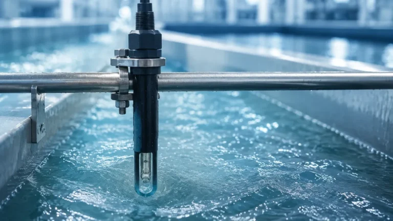
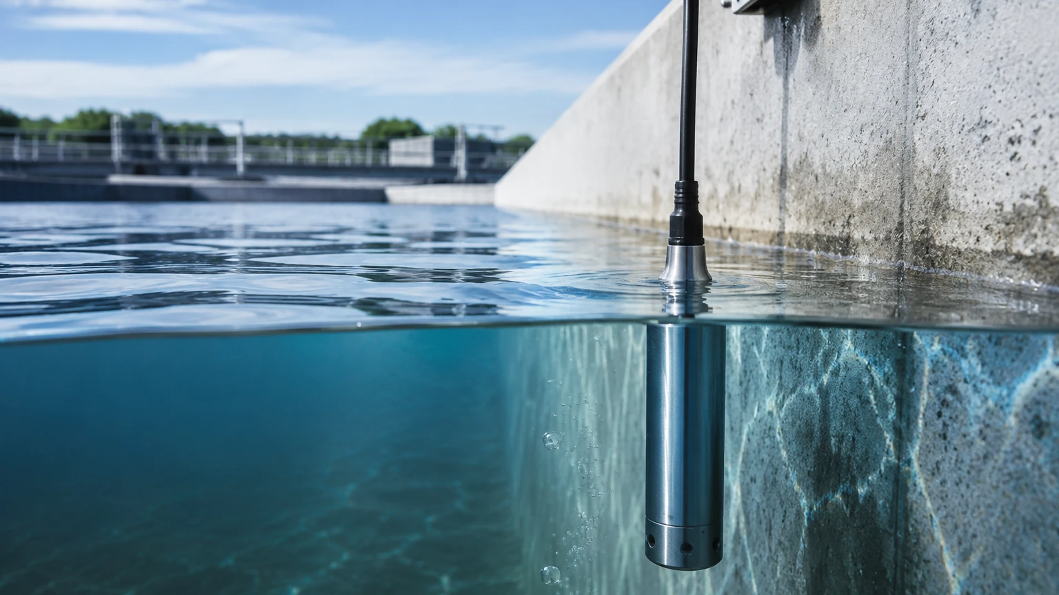
These sensors are designed to be lowered directly into the liquid. The sensing element is housed in a waterproof casing (typically stainless steel or specialized plastics like PVDF). A high-strength, vented cable provides both the electrical signal path and the atmospheric reference. Submersible sensors are ideal for deep wells, boreholes, reservoirs, and wastewater lift stations where external tank mounting is not feasible.
2. Externally Mounted Pressure Transmitters
For tanks with bottom or side-wall access, an external pressure transmitter is used. These are mounted via threaded or flanged connections at the lowest point of the vessel. The diaphragm of the sensor is in direct contact with the process fluid. These are common in chemical processing and food and beverage applications where internal tank obstructions must be avoided.
Key Selection Criteria for Industrial Applications
Selecting the correct hydrostatic sensor requires a detailed analysis of the process environment. Failure to account for chemical compatibility or pressure ranges can lead to premature sensor failure or inaccurate data.
Media Compatibility and Material Construction
The sensor diaphragm and housing must be resistant to the process fluid.
* 316L Stainless Steel: Standard for water and non-corrosive oils.
* Ceramic Diaphragms: Highly resistant to abrasion and many aggressive chemicals.
* Hastelloy or Tantalum: Required for highly corrosive acids or specialized chemical processes.
* Cable Materials: For submersible units, PVC is suitable for water, while PUR (Polyurethane) or FEP (Fluorinated Ethylene Propylene) is required for fuels and chemicals.
Pressure Range and Accuracy
Sensors should be selected so that the maximum expected liquid height corresponds to approximately 75-90% of the sensor’s full-scale range. This provides a buffer for overpressure events while maintaining high resolution. For example, a tank that is 10 meters (32.8 feet) high requires a sensor rated for at least 1 bar (14.5 psi) of hydrostatic pressure.
Temperature Compensation
Liquid density changes with temperature. Advanced hydrostatic sensors include integrated temperature compensation to adjust the level calculation if the liquid's density fluctuates significantly across the operating range. Most industrial sensors operate reliably between -20°C and +80°C, though specialized high-temperature versions are available.
Practical Selection Table
| Application | Recommended Sensor Type | Diaphragm Material | Key Consideration |
| :— | :— | :— | :— |
| Deep Groundwater Well | Submersible Probe | 316L Stainless Steel | Vented cable length and tensile strength |
| Wastewater Sump | Submersible (Clog-resistant) | Ceramic | Resistance to solids and buildup |
| Chemical Storage Tank | Flanged External Transmitter | Hastelloy / PTFE | Chemical compatibility of seals |
| Fuel Storage | Submersible | 316L / PUR Cable | Explosion-proof (ATEX/IECEx) rating |
| Potable Water Tank | Submersible or External | Food-grade Stainless | Sanitary certifications (NSF/FDA) |
Installation Guidelines and Best Practices
Correct installation is critical to the longevity and accuracy of a hydrostatic sensor. Engineers should follow these standard industrial practices:
1. Atmospheric Venting
For submersible sensors, the vent tube inside the cable must remain unobstructed. It should terminate in a dry environment, often using a desiccant bellows or a specialized junction box to prevent moisture from entering the tube. Moisture in the vent tube can cause internal corrosion or lead to measurement drift.
2. Avoiding Turbulence
In tanks with agitators or high-flow inlets, the sensor should be protected from physical turbulence. A "stilling well" (a pipe with small holes to allow liquid entry but dampen waves) is recommended to prevent the sensor from moving or experiencing erratic pressure spikes.
3. Mounting Position
The sensor must be mounted at a known fixed point. In submersible applications, the sensor should not rest on the bottom if silt or sediment accumulation is expected, as this can bury the diaphragm and lead to false readings. A clearance of 100mm to 300mm from the bottom is standard.
4. Cable Protection
Submersible cables should be secured with appropriate hangers or clamps to prevent the weight of the cable from straining the internal wiring. In outdoor installations, conduit should be used to protect the cable from UV degradation and mechanical damage.
Limitations and Operating Constraints
While highly versatile, hydrostatic sensors have specific limitations that must be understood during the engineering phase:
* Density Sensitivity: Since the sensor measures weight, any change in liquid density (due to concentration changes or temperature) will result in a level error. If the density is not constant, a different technology, such as radar, may be more appropriate.
* Pressurized Vessels: In a sealed, pressurized tank, a single hydrostatic sensor cannot distinguish between the liquid's weight and the overhead gas pressure. In these cases, a differential pressure (DP) transmitter is required to subtract the top pressure from the bottom pressure.
* Solid Content: High concentrations of suspended solids or "sludge" can coat the diaphragm, dampening the pressure response or causing a permanent offset.
Comparison with Other Level Technologies
| Feature | Hydrostatic Sensor | Ultrasonic Sensor | Radar Level Meter |
| :— | :— | :— | :— |
| Contact | Contacting | Non-contacting | Non-contacting |
| Foam Influence | Minimal | High | Low to Moderate |
| Vapor/Steam | No Effect | High Effect | Minimal Effect |
| Cost | Low to Moderate | Moderate | Moderate to High |
| Maintenance | Periodic cleaning | Low | Very Low |
Frequently Asked Questions (FAQ)
Q: How often should a hydrostatic sensor be calibrated?
A: In standard water applications, annual calibration is usually sufficient. In corrosive or high-precision chemical processes, bi-annual checks are recommended to account for potential diaphragm fatigue or drift.
Q: Can a hydrostatic sensor be used in a tank with a vacuum?
A: Standard hydrostatic sensors are not designed for vacuum service. A differential pressure transmitter with a remote seal is the preferred solution for vacuum or high-pressure vessels.
Q: What is the maximum depth a submersible sensor can measure?
A: Industrial sensors are available for ranges exceeding 200 meters (approx. 650 feet). The primary constraint is the cable's ability to support its own weight and the pressure rating of the sensing element.
Q: Does the shape of the tank affect the reading?
A: No. Hydrostatic pressure depends only on the vertical height of the liquid, not the volume or shape of the container. However, if you need to calculate volume (liters/gallons), the tank geometry must be programmed into the receiving controller or PLC.
Conclusion
The hydrostatic sensor remains a cornerstone of industrial level measurement due to its simplicity and reliability. By understanding the relationship between pressure and depth, and carefully selecting materials compatible with the process media, engineers can implement long-term monitoring solutions that require minimal intervention. For organizations looking to integrate these sensors into broader automation frameworks, it is essential to consult with a professional manufacturer to ensure all technical specifications meet the site requirements. To explore a wide range of industrial measurement instruments and technical support, you may Review product options and application support on our Main Page.