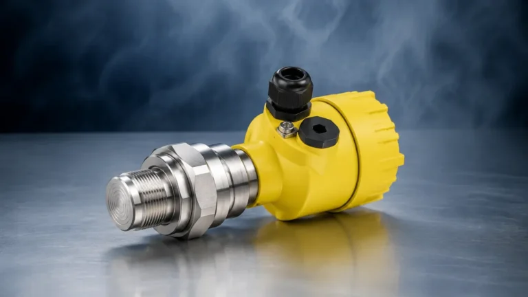
Pressure Transducer Digital
Pressure Transducer Digital
In the landscape of industrial automation and process control, the transition from traditional analog signaling to digital communication has redefined how data is collected and utilized. A pressure transducer digital system—often referred to interchangeably as a digital pressure transmitter—integrates a sensing element with sophisticated electronics to provide a high-resolution, noise-resistant output. Unlike legacy 4-20mA or 0-10V analog sensors, digital transducers offer bidirectional communication, allowing for remote diagnostics, multi-variable reporting, and simplified integration into modern SCADA and PLC architectures.
For engineers and system integrators, selecting the correct digital pressure instrument requires an understanding of the underlying sensing physics, the communication protocols available, and the specific environmental demands of the application. This guide examines the technical foundations, selection criteria, and practical implementation of digital pressure measurement technologies.
Measurement Principles and Digital Conversion
At its core, a digital pressure transducer still relies on physical phenomena to detect pressure changes. However, the internal processing distinguishes it from its analog predecessors. The measurement process typically follows three primary stages: sensing, amplification/compensation, and digitization.
Sensing Technologies
The most common sensing elements used in industrial digital transducers include:
- Piezoresistive Strain Gauges: These utilize a silicon or metal diaphragm with resistors diffused into the surface. When pressure deforms the diaphragm, the resistance changes. These are highly sensitive and widely used for both general-purpose and high-precision applications.
- Capacitive Sensors: These measure the change in capacitance between a flexible sensing diaphragm and a fixed plate. Capacitive sensors are known for their robustness and ability to handle high overpressure conditions.
- Resonant Wire/Crystal: These measure the change in frequency of a vibrating element under tension. While less common, they offer extreme stability for custody transfer or laboratory-grade measurements.
The Digital Signal Chain
In a digital transducer, the low-level signal from the sensor (often in millivolts) is immediately processed by an internal Micro-Processing Unit (MPU). This unit performs several critical functions:
1. Analog-to-Digital Conversion (ADC): The raw signal is converted into a high-resolution digital value (typically 16-bit to 24-bit).
2. Temperature Compensation: The MPU uses an internal temperature sensor to correct for thermal drift in real-time, ensuring accuracy across a wide operating range (e.g., -40°C to +85°C).
3. Linearization: Digital algorithms correct for non-linearity inherent in the sensing element, providing a more accurate output across the full scale.
4. Protocol Encoding: The processed data is packaged into a specific digital protocol, such as Modbus RTU or HART, for transmission over the network.
Digital Communication Protocols
The value of a pressure transducer digital unit lies in its ability to communicate more than just a single pressure value. Depending on the protocol, the device can transmit device status, temperature data, and even maintenance alerts.
Common Industrial Interfaces
- RS485 / Modbus RTU: This is a staple in industrial automation. It allows for long-distance communication (up to 1,200 meters) and supports multi-drop networking, where multiple transducers can be connected to a single pair of wires.
- HART (Highway Addressable Remote Transducer): A hybrid protocol that superimposes a digital signal on a standard 4-20mA loop. This is ideal for upgrading legacy plants without replacing existing wiring.
- IO-Link: A point-to-point digital interface designed for "Industry 4.0." It is increasingly popular in factory automation for its plug-and-play capabilities and extensive diagnostic data.
- CANbus / CANopen: Frequently used in mobile hydraulics and automotive applications due to its high vibration resistance and robust error checking.
Comparison of Digital Protocols
| Protocol | Typical Distance | Topology | Best Use Case |
| :— | :— | :— | :— |
| Modbus RTU | 1,200 m | Daisy-chain (Multi-drop) | Water treatment, remote tank farms |
| HART | 3,000 m | Point-to-point / Multi-drop | Oil & Gas, Chemical processing |
| IO-Link | 20 m | Point-to-point | Food & Beverage, Machine building |
| CANopen | 40 m – 1,000 m | Bus | Mobile machinery, heavy equipment |
Selection Criteria for Digital Pressure Transducers
When evaluating a digital pressure transducer for a specific project, technical specifications must be matched to the process conditions. For those managing complex systems, visiting the Main Page of a dedicated manufacturer can provide a comprehensive overview of how these sensors integrate into broader level and flow measurement solutions.
Pressure Range and Type
Identify the maximum expected pressure and choose a sensor with a range approximately 20% higher to account for pressure spikes. You must also specify the pressure type:
- Gauge Pressure: Referenced to atmospheric pressure.
- Absolute Pressure: Referenced to a vacuum.
- Differential Pressure: Measures the difference between two points.
Media Compatibility
The wetted parts (the materials that touch the process fluid) must be chemically compatible. Standard materials include 316L stainless steel, but aggressive chemicals may require Hastelloy, Monel, or Tantalum diaphragms. For water treatment applications, standard stainless steel is usually sufficient, whereas oil and gas applications may require NACE-compliant materials.
Accuracy and Resolution
Digital transducers often boast higher accuracy than analog versions because they eliminate the errors associated with digital-to-analog conversion at the sensor and analog-to-digital conversion at the PLC. Look for "Total Error Band" (TEB) specifications, which include linearity, hysteresis, repeatability, and temperature effects.
Installation and Integration Considerations
Proper installation is critical to maintaining the accuracy and longevity of a digital pressure transducer. Digital electronics are sensitive to environmental factors that might not affect simple mechanical gauges.
Mounting and Orientation
While many digital transducers are vibration-resistant, they should be mounted away from heavy pumps or reciprocating compressors whenever possible. If the sensor is mounted in a position where moisture can collect, ensure the cable entry points downward to create a drip loop. For liquid applications, mount the sensor below the tap to prevent air bubbles from affecting the reading; for gas applications, mount it above the tap to prevent condensate buildup.
Wiring and Shielding
Digital signals, particularly RS485 and IO-Link, require high-quality shielded twisted-pair (STP) cabling. The shield should be grounded at a single point (usually the PLC or gateway side) to prevent ground loops. In environments with high Electromagnetic Interference (EMI)—such as near Variable Frequency Drives (VFDs)—digital signals are generally more robust than 4-20mA signals, but proper shielding remains mandatory.
Calibration and Zero-Tracking
One significant advantage of digital transducers is the ability to perform a "digital zero." Over time, all sensors experience a slight shift in their zero-point. With a digital interface, a command can be sent from the PLC to re-zero the sensor without needing to access the device physically, provided the process pressure is known to be at zero.
Applications in Level Measurement
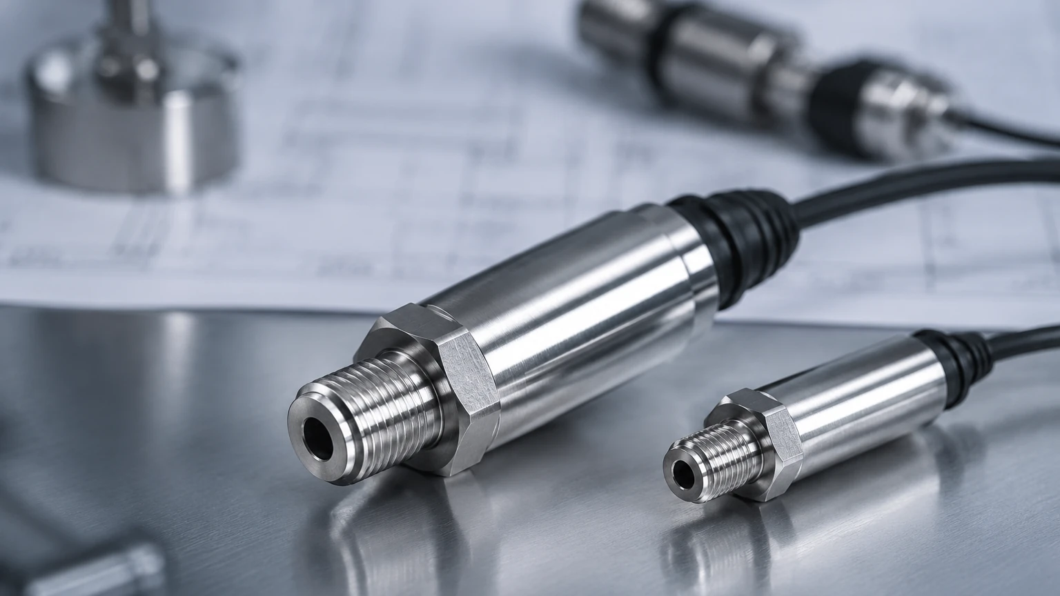
Digital pressure transducers are frequently utilized as hydrostatic level transmitters. In this application, the sensor measures the pressure exerted by a liquid column. The relationship is defined by the formula:
P = ρ × g × h
*(Where P is pressure, ρ is liquid density, g is gravity, and h is the height of the liquid.)*
In deep wells or large storage tanks, a digital hydrostatic transmitter can transmit both the level and the liquid temperature over a single RS485 line. This is particularly useful in water treatment and chemical storage where density may change with temperature, allowing the PLC to calculate a temperature-compensated volume measurement accurately.
Limitations and Potential Risks
Despite their advantages, digital transducers are not universal solutions. Engineers should be aware of the following limitations:
1. Latency: Digital processing and bus communication introduce a small amount of latency (typically milliseconds). While negligible for most process industries, it may be a factor in high-speed hydraulic control loops.
2. Complexity: Configuring a Modbus network requires more technical knowledge than wiring a simple two-wire analog loop. Factors like baud rates, parity, and slave IDs must be correctly managed.
3. Power Requirements: Digital transducers often require more current to power the internal microprocessor and communication hardware than a basic analog sensor. Ensure the power supply is sized correctly for the entire network of devices.
4. Firmware Dependencies: Unlike a purely mechanical or analog device, a digital transducer runs on firmware. It is important to source instruments from reliable manufacturers like Welk to ensure the firmware is stable and complies with industry standards.
Frequently Asked Questions (FAQs)
Q: Can I use a digital pressure transducer in hazardous areas?
A: Yes, many digital transducers are available with ATEX, IECEx, or UL certifications for intrinsically safe or explosion-proof installations. HART-based digital sensors are particularly common in these environments.
Q: How far can I run the signal from a digital pressure transducer?
A: This depends on the protocol. RS485 (Modbus) can reach 1,200 meters (approx. 4,000 feet) without a repeater. IO-Link is limited to 20 meters. For very long distances, digital signals are far superior to analog voltage signals, which suffer from significant voltage drops.
Q: Is a digital pressure transducer more accurate than an analog one?
A: Generally, yes. Because the signal remains in a digital format from the sensor head to the control system, there is no signal degradation or loss of resolution due to electrical noise or long cable runs.
Q: What happens if the communication is lost?
A: Most digital protocols include error-checking (like CRC in Modbus). If the PLC stops receiving valid data packets, it can be programmed to trigger a fail-safe state. This is more reliable than an analog signal, which might simply drift to an incorrect value without the system detecting a fault.
By integrating a pressure transducer digital into your process, you gain access to a wealth of data that can improve efficiency, reduce downtime through predictive maintenance, and ensure higher precision in critical measurements. Whether for simple tank level monitoring or complex chemical processing, the shift to digital instrumentation represents a significant step forward in industrial reliability.