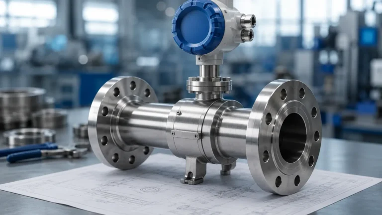
API 2350 5th Edition Aops Sil 2
API 2350 5th Edition Aops Sil 2
In the petroleum and chemical processing industries, the prevention of tank overfills is a critical safety and environmental priority. The API 2350 standard, specifically the 5th edition, provides the industry-standard framework for managing these risks. Central to this standard is the implementation of an Automated Overfill Prevention System (AOPS), which often requires compliance with Safety Integrity Level 2 (SIL 2) to ensure high reliability. Understanding the intersection of API 2350 5th edition AOPS SIL 2 requirements is essential for engineers and facility managers responsible for bulk liquid storage.
Understanding API 2350 5th Edition and AOPS
The American Petroleum Institute (API) Standard 2350, "Overfill Protection for Storage Tanks in Petroleum Facilities," defines the minimum requirements for preventing tanks from being overfilled. The 5th edition, published in 2020, significantly aligned the standard with international functional safety standards like IEC 61511.
An Automated Overfill Prevention System (AOPS) is a safety instrumented system (SIS) designed to automatically detect a high-level condition and initiate a response to terminate the flow into the tank before an overfill occurs. Unlike a basic process control system (BPCS) used for daily inventory management, an AOPS must be independent and dedicated solely to safety functions. Under the 5th edition, the requirement for an AOPS is determined by the tank category (Category 1, 2, or 3), which is based on the level of automation and the presence of personnel at the facility.
Measurement Principles for Overfill Prevention
Before selecting instrumentation for an AOPS, it is vital to understand the underlying measurement principles. Reliability in an AOPS context depends on the sensor's ability to operate accurately in potentially turbulent or vapor-heavy environments.
1. Radar Level Measurement (Non-Contact)
Radar level meters utilize Time of Flight (ToF) technology. High-frequency microwave signals (typically 26 GHz or 80 GHz) are emitted from the antenna, reflected off the liquid surface, and received back. The distance is calculated based on the travel time. For AOPS, radar is preferred because it has no moving parts and is largely unaffected by changes in density, temperature, or pressure. Frequency-Modulated Continuous Wave (FMCW) radar provides high precision, which is necessary for identifying the exact "High-High" (HH) trip point.
2. Ultrasonic Level Measurement
Ultrasonic sensors emit sound waves that bounce off the liquid surface. While cost-effective for water-based applications, they are sensitive to vapor blankets and temperature fluctuations common in petroleum storage. In the context of API 2350 5th edition AOPS SIL 2, ultrasonic sensors are less common than radar but may be used in atmospheric tanks with stable environments.
3. Point Level Switches (Vibrating Fork)
Level switches serve as the final "stop" mechanism. A vibrating fork sensor oscillates at a specific frequency. When the liquid reaches the fork, the frequency changes, triggering an alarm or a shutdown signal. These are highly reliable for safety applications because they provide a binary (on/off) signal that is easily integrated into a safety logic solver.
4. Hydrostatic Pressure Measurement
Hydrostatic transmitters measure the pressure exerted by the liquid column. While accurate for level, they depend on the density of the fluid. If the product density changes, the level calculation will shift, which can be a limitation for multi-product tanks governed by API 2350.
The Role of SIL 2 in Automated Overfill Prevention Systems
Safety Integrity Level (SIL) is a measure of the reliability and performance of a Safety Instrumented Function (SIF). API 2350 5th edition references the need for functional safety assessments. When a risk assessment determines that a manual or basic automated system is insufficient, a SIL-rated AOPS is required.
SIL 2 indicates a Probability of Failure on Demand (PFD) between 0.01 and 0.001. Achieving SIL 2 compliance for an AOPS involves several factors:
* Device Certification: Sensors, logic solvers, and final elements (valves) must be certified for use in SIL 2 environments by third parties (e.g., exida or TÜV).
* Redundancy: While a single certified device can sometimes achieve SIL 2, many engineers prefer a 1oo2 (one out of two) or 2oo3 voting logic to increase both safety and availability.
* Independence: The AOPS must be physically and electrically separate from the tank gauging system used for inventory. This ensures that a failure in the inventory system does not disable the overfill protection.
Selection Criteria for AOPS Instrumentation
Choosing the right equipment is the most critical step in meeting API 2350 5th edition AOPS SIL 2 standards. The following table compares common technologies used in these safety systems.
| Technology | Suitability for SIL 2 | Pros | Cons | Typical Use in AOPS |
| :— | :— | :— | :— | :— |
| 80 GHz Radar | High (Certified models) | Non-contact, high precision, handles vapors well. | Higher initial cost. | Continuous level monitoring for HH alarm. |
| Vibrating Fork Switch | High (Certified models) | Simple, robust, independent of fluid properties. | Point level only; no continuous data. | Independent High-High trip switch. |
| Guided Wave Radar | High | Unaffected by foam or turbulence. | Contact with fluid; may collect debris. | Small tanks or bypass chambers. |
| Ultrasonic | Moderate | Low cost, easy installation. | Sensitive to vapor and wind. | Non-hazardous, atmospheric water tanks. |
| Hydrostatic | Moderate | Reliable for known densities. | Density-dependent; requires tank penetration. | Backup level measurement. |
For engineers reviewing hardware options, the Main Page of a specialized manufacturer provides detailed data sheets on SIL-rated radar and switch technologies that align with these requirements.
Installation and Engineering Requirements
Compliance with API 2350 5th edition goes beyond choosing a SIL 2 rated sensor; it requires proper engineering and installation.
1. Stilling Wells and Bypass Chambers: For tanks with internal obstructions or heavy turbulence, radar sensors should be installed in stilling wells. This ensures a clean signal and prevents the "false echoes" that could lead to a failure to trip.
2. Mounting Position: Sensors must be positioned to avoid the "dead zone" (the area too close to the sensor where measurement is impossible) and should not be placed directly under the fill stream.
3. Environmental Protection: In petroleum facilities, instruments must be explosion-proof (ATEX/IECEx) and capable of withstanding ambient temperatures ranging from -40°C to +70°C.
4. Logic Solver Integration: The sensor signal must be sent to a dedicated safety logic solver, not the standard PLC. This solver then commands the final element—typically an emergency shutdown valve (ESV)—to close.
Maintenance, Proof Testing, and Limitations
A SIL 2 rating is not a permanent status; it is maintained through a rigorous lifecycle management process as defined in API 2350 5th edition.
* Proof Testing: This is a periodic test performed to detect dangerous hidden failures. For an AOPS, this usually involves a "wet test" where the level is physically raised to trigger the sensor, or a "dry test" using electronic simulation features built into modern radar meters.
* Proof Test Interval: The frequency of these tests (e.g., every 12 months) is determined during the initial SIL calculation. Missing a proof test invalidates the SIL 2 rating.
* Response Time: The system must be fast enough to close the inlet valve before the liquid reaches the critical overfill level. This requires calculating the maximum fill rate against the tank's remaining volume at the HH trip point.
Limitations
While an AOPS significantly reduces risk, it cannot account for structural failures of the tank or human errors during the maintenance of the safety system itself. Furthermore, if the product in the tank is changed to one with significantly different dielectric properties, the radar sensors may require recalibration to maintain accuracy.
Frequently Asked Questions (FAQ)
Q: Can I use my existing inventory radar for API 2350 AOPS?
A: Generally, no. API 2350 5th edition emphasizes independence. The AOPS sensor should be a separate device from the one used for daily inventory to prevent common-cause failures.
Q: Is SIL 2 mandatory for all tanks under API 2350?
A: Not necessarily. The need for SIL 2 is determined by a Risk Assessment (such as LOPA). However, for Category 3 tanks (unattended), a SIL 2 AOPS is often the most practical way to meet the risk reduction requirements.
Q: What is the difference between AOPS and a high-level alarm?
A: A high-level alarm (HLA) notifies an operator to take action. An AOPS (Automated Overfill Prevention System) takes action automatically, such as closing a valve or stopping a pump, without human intervention.
Q: How do metric units apply to API 2350 calculations?
A: While the standard originated in the US, it is used globally. Most engineering firms calculate the "Critical High" (CH) and "Safe Fill" levels in millimeters (mm) or meters (m) to ensure precision, especially when determining the response time for high-speed filling operations.
For those seeking to implement these systems, focusing on the integration of API 2350 5th edition AOPS SIL 2 compliant hardware is the most effective path toward operational safety and regulatory adherence.