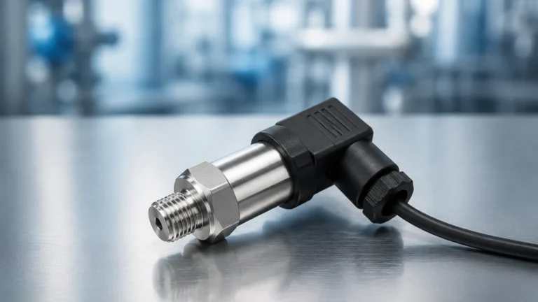
Dp Flow Meter
Dp Flow Meter
Differential pressure (DP) flow measurement remains one of the most prevalent and trusted methods for quantifying fluid movement in industrial processes. Despite the emergence of ultrasonic and Coriolis technologies, the dp flow meter continues to dominate heavy industries such as oil and gas, water treatment, and chemical processing due to its reliability, lack of moving parts, and well-understood physics. This guide provides an engineering-focused overview of DP flow measurement, its relationship to hydrostatic level sensing, and the criteria necessary for selecting the appropriate instrumentation for complex process environments.
Fundamental Principles of Differential Pressure Measurement
The operation of a dp flow meter is based on Bernoulli’s principle, which states that as the speed of a moving fluid increases, the pressure within the fluid decreases. In a closed pipe, this is achieved by introducing a physical restriction (a primary element) that forces the fluid to accelerate.
When the fluid passes through this restriction, its kinetic energy increases at the expense of its static pressure. By measuring the pressure before the restriction ($P_1$) and immediately after it ($P_2$), the differential pressure ($ΔP$) can be determined. The relationship between the flow rate ($Q$) and the differential pressure is expressed by the following simplified equation:
$$Q = k \cdot \sqrt{\Delta P}$$
Where:
* Q is the flow rate.
* k is a flow coefficient determined by the geometry of the restriction and fluid properties.
* ΔP is the measured pressure drop ($P_1 – P_2$).
Because the flow rate is proportional to the square root of the differential pressure, the "turndown ratio" (the range between maximum and minimum measurable flow) of a standard dp flow meter is often more limited than other technologies, typically ranging from 3:1 to 5:1 unless advanced multi-variable transmitters are employed.
Primary Elements: Hardware for Flow Restriction
The accuracy and performance of a dp flow meter depend largely on the "primary element"—the hardware that creates the pressure drop. Choosing the right element requires balancing cost, permanent pressure loss, and fluid characteristics.
1. Orifice Plates
The orifice plate is a thin metal disc with a precision-machined hole (bore) in the center. It is the most common primary element due to its low cost and ease of installation between standard pipe flanges. However, it creates a significant permanent pressure loss and is susceptible to wear over time, which can degrade accuracy.
2. Venturi Tubes
Venturi tubes consist of a converging conical section, a throat, and a diverging recovery section. They are designed to minimize permanent pressure loss and are highly resistant to erosion. Venturi tubes are ideal for large-diameter pipes and applications involving slurries or fluids with suspended solids, though they are significantly more expensive and larger than orifice plates.
3. Flow Nozzles
Flow nozzles are often used in high-velocity applications, such as steam flow in power plants. They offer better pressure recovery than orifice plates and are more durable under high-temperature and high-pressure conditions.
4. Pitot Tubes and Averaging Pitot Tubes
Unlike the previous elements that restrict the entire flow stream, pitot tubes measure the difference between static pressure and impact pressure at a specific point. Averaging pitot tubes use multiple sensing ports across the pipe diameter to provide a more representative flow profile, offering very low pressure loss but lower accuracy in turbulent conditions.
Selection Criteria for Industrial Applications
Selecting a dp flow meter requires a comprehensive evaluation of the process conditions. The following table provides a comparison of the most common primary elements to assist in initial engineering assessments.
| Feature | Orifice Plate | Venturi Tube | Flow Nozzle | Pitot Tube |
| :— | :— | :— | :— | :— |
| Accuracy | Good (1-2%) | Excellent (0.5-1%) | Good (1-1.5%) | Fair (2-4%) |
| Pressure Loss | High | Low | Medium | Very Low |
| Cost | Low | High | Medium | Low |
| Suitability for Slurries | Poor | Excellent | Fair | Poor |
| Installation Length | Short | Long | Medium | Short |
| Maintenance | Periodic Inspection | Low | Low | Low |
When reviewing technical specifications, engineers should also consider the Reynolds number of the fluid. Most DP elements require a minimum Reynolds number (often >10,000) to ensure a stable flow profile and predictable discharge coefficients.
Installation Engineering and Best Practices
The performance of a dp flow meter is highly sensitive to how it is installed. Improper piping can lead to measurement errors exceeding 10%.
Straight Pipe Runs
To ensure a fully developed and symmetrical flow profile, DP meters require straight lengths of pipe both upstream and downstream of the primary element. A general rule of thumb is 10 to 20 pipe diameters (D) upstream and 5D downstream. If the piping includes elbows, valves, or pumps close to the meter, flow conditioners or longer straight runs may be required.
Impulse Line Configuration
Impulse lines (small-bore tubing) connect the primary element to the differential pressure transmitter. Their configuration depends on the fluid state:
* Liquids: The transmitter should be mounted below the pipe to allow air bubbles to rise back into the process line.
* Gases: The transmitter should be mounted above the pipe to allow condensed moisture to drain back into the process line.
* Steam: Condensate pots are required to protect the transmitter from high temperatures, ensuring the impulse lines are filled with water rather than live steam.
Manifolds
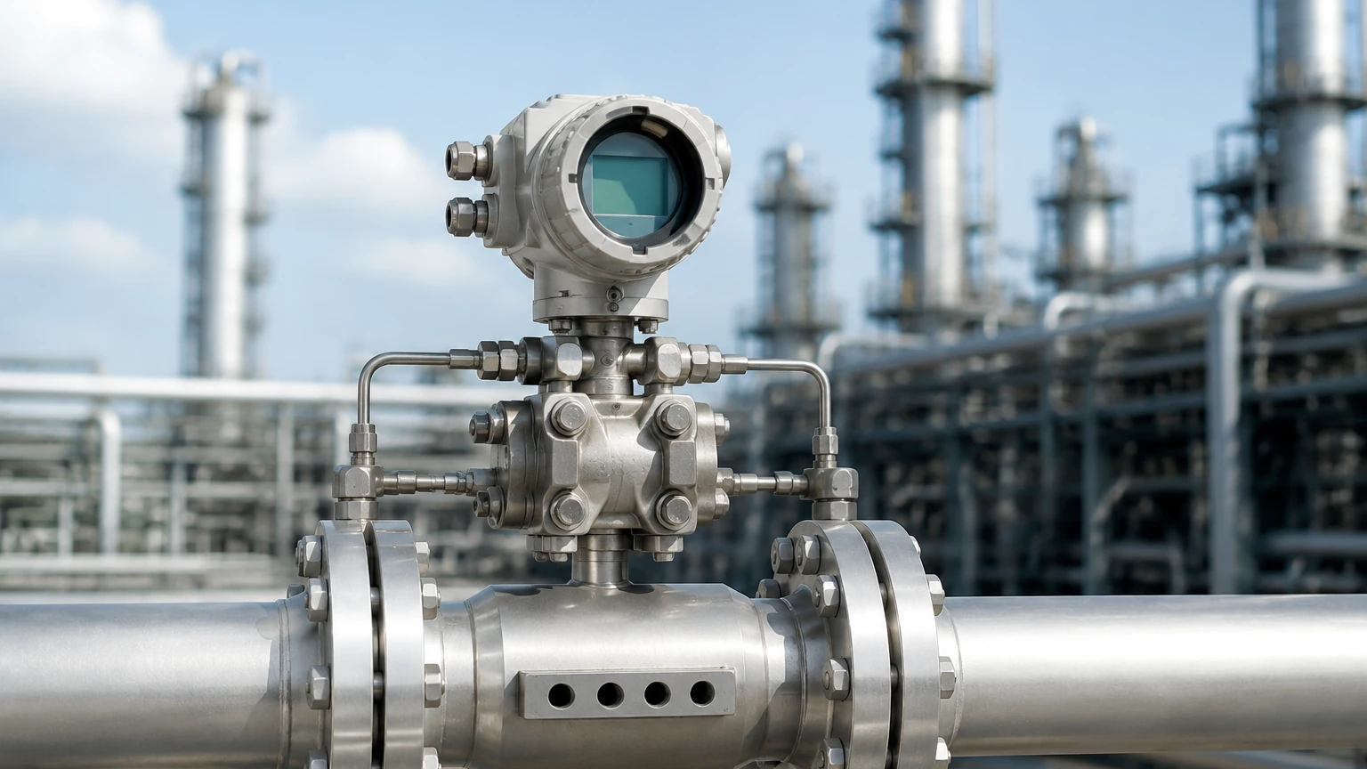
A 3-valve or 5-valve manifold is essential for every DP installation. It allows for the isolation of the transmitter for maintenance and provides an equalization valve to zero the instrument under line pressure without stopping the process flow.
Integration with Level Measurement Systems
There is a deep technological overlap between flow measurement and level measurement. In many industrial tanks, especially pressurized vessels, differential pressure is the primary method for determining liquid level. This is known as hydrostatic level measurement.
In these applications, the DP transmitter measures the pressure exerted by the liquid column (the "head") against a reference pressure (either atmospheric for open tanks or the vapor space pressure for closed tanks). Because Welk specializes in high-precision industrial instrumentation, understanding this crossover is vital. For engineers looking to integrate these technologies into broader process automation frameworks, it is helpful to consult a Main Page of a specialized manufacturer like Welk to understand the compatibility between flow transmitters and level sensing arrays.
For example, a hydrostatic level transmitter and a DP flow transmitter often share the same internal sensor architecture. The primary difference lies in the software configuration (square root extraction for flow vs. linear for level) and the physical installation of the primary element.
Limitations and Common Risks
While robust, the dp flow meter is not a "fit and forget" solution. Engineers must be aware of the following risks:
1. Permanent Pressure Loss (PPL): Unlike ultrasonic or magnetic meters, DP meters extract energy from the system. In high-volume pumping applications, the energy cost of overcoming the pressure drop created by an orifice plate can be significant over the lifespan of the plant.
2. Clogging and Fouling: Orifice plates and pitot tubes can easily clog if the fluid contains large solids or becomes viscous. In these cases, a wedge-type DP meter or a Venturi tube is preferred.
3. Square Root Relationship: At the lower end of the flow range (e.g., below 20% of maximum flow), the differential pressure signal becomes very small. Small errors in pressure measurement are magnified when the square root is calculated, leading to poor accuracy at low flow rates.
4. Density Sensitivity: DP meters measure mass flow indirectly. If the fluid density changes due to temperature or pressure fluctuations, the volumetric flow calculation will be incorrect unless a multi-variable transmitter with integrated temperature and pressure compensation is used.
Frequently Asked Questions (FAQs)
Q: How often should an orifice plate be inspected?
A: In non-corrosive, clean liquid service, annual inspections are usually sufficient. In abrasive or steam service, the sharp edge of the orifice can round off, leading to an under-registration of flow. These should be checked every six months.
Q: Can a dp flow meter measure bi-directional flow?
A: Standard primary elements like orifice plates and Venturi tubes are unidirectional. However, specialized bi-directional pitot tubes or symmetrical wedge meters can be used for bi-directional applications when paired with a transmitter capable of measuring negative differential pressure.
Q: What is the maximum temperature for a DP flow system?
A: The limit is usually defined by the impulse line and manifold materials rather than the transmitter itself. By using remote seals or extended impulse lines, DP meters can measure fluids exceeding 500°C (932°F).
Q: Why is my DP flow meter reading high when the pump is off?
A: This is often due to "zero drift" or trapped air/liquid in the impulse lines. Ensure the impulse lines are properly bled and use the manifold to re-zero the transmitter at line pressure.
Conclusion
The dp flow meter remains a cornerstone of industrial process control due to its versatility and the vast body of engineering standards (such as ISO 5167) that govern its use. By carefully selecting the primary element and adhering to strict installation guidelines regarding straight pipe runs and impulse line orientation, engineers can achieve highly accurate and repeatable measurements. Whether used for steam balancing, water distribution, or as a complement to hydrostatic level systems, the differential pressure method provides a cost-effective and durable solution for modern automation needs.