Differential Pressure Transducer
Differential Pressure Transducer
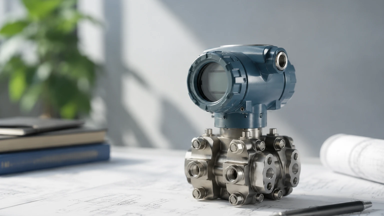
In the field of industrial process control, the differential pressure transducer remains one of the most versatile and widely implemented instruments for level, flow, and pressure measurement. While modern non-contact technologies like radar have gained popularity, the differential pressure (DP) method provides a robust, cost-effective, and highly accurate solution for pressurized vessels, steam drums, and complex chemical reactors. This guide examines the fundamental principles, application configurations, and engineering considerations essential for selecting and installing a differential pressure transducer in industrial environments.
Measurement Principles of Differential Pressure
The operation of a differential pressure transducer is based on the principle of hydrostatic pressure. In a liquid column, the pressure exerted at the base is directly proportional to the height of the liquid and its density. The mathematical relationship is expressed as:
P = ρ × g × h
Where:
* P is the hydrostatic pressure.
* ρ (rho) is the density of the fluid.
* g is the acceleration due to gravity (approximately 9.81 m/s²).
* h is the height of the liquid column.
In an open-to-atmosphere tank, a simple pressure transmitter at the bottom can determine the level. However, in a closed or pressurized vessel, the total pressure at the bottom is the sum of the liquid's hydrostatic pressure plus the blanketing gas pressure. To isolate the liquid level, the gas pressure must be subtracted.
A differential pressure transducer achieves this by utilizing two sensing ports: the High-Pressure (HP) side and the Low-Pressure (LP) side. By connecting the HP side to the bottom of the tank and the LP side to the gas space at the top, the transducer mechanically or electronically cancels out the common gas pressure, leaving only the pressure generated by the liquid height.
System Configurations: Wet Leg vs. Dry Leg
When applying a differential pressure transducer to a closed vessel, the method used to connect the LP port to the vapor space is critical. The choice depends on whether the vapor in the tank will condense at ambient temperatures.
Dry Leg Systems
If the gas or vapor in the tank does not condense at the temperature of the impulse lines (the small-diameter pipes connecting the tank to the transducer), a "dry leg" is used. The LP impulse line remains filled with gas. The transducer measures the difference between the total pressure at the bottom and the gas pressure at the top. If condensation occurs in a dry leg, it creates an erratic liquid head on the LP side, leading to significant measurement errors.
Wet Leg Systems
In applications involving steam or vapors that condense readily (such as in a boiler drum), a "wet leg" is required. The LP impulse line is intentionally filled with a reference fluid (usually the process condensate or a stable oil). This creates a constant, known pressure on the LP side. The transducer then measures the difference between the variable head at the tank bottom and the fixed head in the wet leg. During calibration, the instrument must be "zero-suppressed" to account for the constant weight of the liquid in the wet leg.
Remote Diaphragm Seals
For highly corrosive, viscous, or high-temperature fluids, impulse lines may clog or leak. In these scenarios, a differential pressure transducer is equipped with remote diaphragm seals. These seals use a flexible diaphragm to isolate the process fluid, transmitting the pressure through a capillary tube filled with silicone oil or another transmission fluid. This configuration eliminates the need for wet or dry legs but introduces temperature-related expansion variables that must be compensated for during the engineering phase.
Key Evaluation and Selection Criteria
Selecting the correct differential pressure transducer requires a detailed understanding of the process conditions. Engineers should evaluate the following parameters before procurement:
1. Pressure Range and Turndown Ratio
The transducer must handle the maximum static pressure of the vessel while remaining sensitive enough to measure small changes in liquid level. The "turndown ratio" refers to the range over which the device can maintain its rated accuracy. For example, a device with a 100:1 turndown can be calibrated to measure a very small fraction of its maximum sensor limit without losing significant precision.
2. Material Compatibility
The wetted parts—specifically the sensing diaphragms and process flanges—must be compatible with the process media. Common materials include 316L Stainless Steel, Hastelloy C, Monel, and Tantalum. For hydrogen service, gold-plated diaphragms are often used to prevent hydrogen permeation, which can cause sensor embrittlement.
3. Accuracy and Long-term Stability
In B2B industrial applications, accuracy is typically defined as a percentage of the calibrated span (e.g., ±0.075%). Long-term stability is equally important, as it dictates how often the instrument requires re-calibration in the field.
4. Environmental and Hazardous Area Ratings
Transducers installed in chemical plants or refineries often require explosion-proof or intrinsically safe certifications (such as ATEX, IECEx, or UL). Additionally, the Ingress Protection (IP) rating should be sufficient for the local environment (e.g., IP66/67 for outdoor or wash-down areas).
Practical Selection Table
| Application Type | Recommended Configuration | Primary Advantage | Limitation |
| :— | :— | :— | :— |
| Open Water Tank | Single-ended Pressure | Lowest cost, simple install | Cannot be used in pressurized vessels |
| Clean, Non-condensing Gas | Dry Leg DP Transducer | High accuracy, low maintenance | Risk of error if condensation occurs |
| Steam / Condensable Vapor | Wet Leg DP Transducer | Reliable in high-temp vapor | Requires periodic refilling of the leg |
| Corrosive / Viscous Media | Remote Diaphragm Seal | Protects sensor from media | Higher cost; sensitive to temp shifts |
| Hygienic / Food & Beverage | Flush Diaphragm Seal | Prevents bacterial growth | Capillary length limits response time |
For a comprehensive overview of available measurement technologies and technical support, professionals can Review product options and application support at the Welk Main Page.
Installation Considerations and Best Practices
The reliability of a differential pressure transducer is often determined more by its installation than by the instrument itself. Proper piping and mounting are essential to prevent measurement drift and signal noise.
* Impulse Line Slope: Impulse lines should be sloped at least 1:10 (or approximately 8%) to allow gas bubbles to rise back into the tank (in liquid service) or to allow condensate to drain back into the tank (in gas service).
* Manifold Valves: A 3-valve or 5-valve manifold should always be installed between the process and the transducer. This allows the instrument to be isolated, zero-checked, and removed for maintenance without shutting down the process.
* Temperature Effects: If using remote seals with capillaries, both capillaries should be kept at the same temperature. Avoid routing one capillary near a heat source (like a steam pipe) while the other is in the shade, as the differential thermal expansion of the fill fluid will cause a false pressure reading.
* Venting and Bleeding: Ensure the transducer housing is oriented so that the vent/drain valves are at the highest point for gas applications and the lowest point for liquid applications.
Common Risks and Limitations
While highly effective, the differential pressure transducer has inherent limitations that must be managed:
1. Density Sensitivity: Since the transducer measures weight (pressure), any change in the fluid's specific gravity—caused by temperature fluctuations or changes in chemical composition—will result in a level error. If the density changes significantly, a secondary temperature sensor or a multivariable transmitter may be required to calculate a compensated level.
2. Impulse Line Clogging: In applications with suspended solids or slurries, impulse lines are prone to plugging. This can be mitigated by using purge systems or switching to remote diaphragm seals.
3. Static Pressure Limits: Every DP transducer has a Maximum Working Pressure (MWP). Exceeding this limit can damage the internal sensor or cause the diaphragm to rupture.
Frequently Asked Questions (FAQ)
Q: How does a differential pressure transducer differ from a standard pressure transmitter?
A: A standard pressure transmitter has one process connection and measures pressure relative to the atmosphere (gauge) or a vacuum (absolute). A differential pressure transducer has two connections and measures the difference in pressure between them, regardless of the overall system pressure.
Q: What is "Zero Elevation" and "Zero Suppression"?
A: These are calibration adjustments. Zero suppression is used when the "zero" level of the tank results in a positive pressure on the transducer (common in wet leg setups). Zero elevation is used when the "zero" level results in a negative pressure relative to the LP side.
Q: Can I use a DP transducer for flow measurement?
A: Yes. By placing an orifice plate or Venturi tube in a pipe, a DP transducer can measure the pressure drop across the restriction, which is proportional to the square of the flow rate.
Q: How often should a differential pressure transducer be calibrated?
A: For most industrial applications, a calibration check every 1 to 2 years is standard. However, in critical safety loops or high-fouling environments, more frequent intervals may be necessary.
Conclusion for Project Stakeholders
Before proceeding with the procurement of a differential pressure transducer, project teams should confirm the exact fluid density at operating temperatures, the maximum vessel pressure, and the physical distance between the mounting point and the vessel. For complex installations, such as those involving vacuum conditions or extreme temperatures, consulting with a specialized manufacturer like Welk ensures that the selected instrument is optimized for long-term performance and safety. By adhering to rigorous installation standards and selecting appropriate diaphragm materials, the DP transducer remains an indispensable tool for accurate industrial level measurement.