Field Orp Sensor
Field Orp Sensor
In the landscape of industrial process control, the ability to monitor the chemical state of a liquid is as critical as monitoring its physical volume. While level measurement technologies, such as those found on the Main Page of industrial instrumentation providers, ensure that tanks do not overflow or run dry, the field ORP sensor provides the qualitative data necessary to manage chemical reactions, disinfection, and wastewater treatment. Oxidation-Reduction Potential (ORP), also known as Redox, is a measure of the cleanliness of the water and its ability to break down contaminants.
A field ORP sensor is specifically designed to withstand the rigors of continuous immersion in industrial environments, ranging from municipal wastewater plants to high-pressure chemical reactors. Unlike laboratory sensors, these field-grade instruments must provide long-term stability, resistance to electrode poisoning, and easy integration into automated control systems.
Understanding Oxidation-Reduction Potential (ORP) Principles
To effectively select and deploy a field ORP sensor, it is essential to understand the underlying electrochemical principles. ORP measurement quantifies the tendency of a chemical species to acquire electrons and thereby be reduced. In practical terms, it measures the "activity" of oxidizers (like chlorine, ozone, or bromine) or reducers (like sodium bisulfite) in a solution.
The Electrochemical Cell
The measurement is performed using an electrochemical cell consisting of two primary components: a measuring electrode and a reference electrode.
1. Measuring Electrode: Usually made of a noble metal, most commonly platinum. The surface of this metal acts as a platform for electron exchange but does not participate in the chemical reaction itself. If the solution contains oxidizers, they will pull electrons from the electrode, creating a positive potential. If reducers are present, they donate electrons, creating a negative potential.
2. Reference Electrode: This provides a stable, constant voltage against which the measuring electrode is compared. The most common reference system is Silver/Silver Chloride (Ag/AgCl) immersed in a concentrated Potassium Chloride (KCl) electrolyte.
The Nernst Equation and Millivolts
The output of a field ORP sensor is a millivolt (mV) signal. Unlike pH measurement, which is temperature-compensated to provide a logarithmic scale (0-14), ORP is typically reported as a raw millivolt value ranging from -2000 mV to +2000 mV. While temperature does affect the speed of the reaction and the activity of the ions, ORP is generally not temperature-compensated in the same way pH is, because the complex nature of redox reactions makes a universal compensation constant impossible for all chemical species.
Components and Design of an Industrial Field ORP Sensor
Industrial field ORP sensors are engineered for durability. A standard laboratory probe would fail within days in a typical industrial application due to junction clogging or mechanical breakage.
Electrode Materials
* Platinum (Pt): The standard for most applications, including water treatment and pool/spa monitoring. It is highly resistant to chemical attack.
* Gold (Au): Used in specific applications where strong oxidizers (like cyanide destruction in mining) might cause the formation of a platinum oxide film on a standard Pt electrode, which would lead to sluggish response times.
Reference Junctions
The junction is the interface where the internal electrolyte of the reference electrode meets the process liquid. In field applications, this is the most common point of failure.
* Porous Teflon (PTFE): Highly resistant to fouling and chemical attack. It allows for a steady flow of electrolyte while preventing the process liquid from entering the sensor.
* Ceramic: A traditional choice for clean water applications, though it can be prone to clogging in high-solids wastewater.
* Double Junction Design: This includes an additional internal chamber to protect the primary Ag/AgCl reference element from "poisoning" by ions like sulfides, cyanides, or heavy metals that might react with the silver.
Body Materials
Field sensors are typically encased in chemically resistant plastics such as Polyphenylene Sulfide (PPS), Polyvinylidene Fluoride (PVDF), or 316L Stainless Steel for high-pressure environments. These materials ensure the sensor can withstand temperatures up to 100°C (212°F) and pressures exceeding 10 bar (145 psi).
Key Selection Criteria for Field Applications
Selecting the right field ORP sensor requires a thorough analysis of the process conditions. Using an incorrectly specified sensor leads to frequent calibration requirements and premature sensor death.
Chemical Compatibility
Identify the primary oxidizers or reducers in the stream. For example, in wastewater denitrification, the ORP values are typically negative (e.g., -100 mV to -200 mV), whereas in chlorine-based disinfection, values are positive (e.g., +600 mV to +800 mV). Ensure the sensor body and seals (O-rings made of Viton or EPDM) are compatible with the process chemicals.
Pressure and Flow Rates
High-velocity flows can cause "streaming potentials," which are fluctuations in the mV reading caused by the movement of ions across the electrode surface. Conversely, low flow can lead to stagnant layers and slow response. Sensors should be rated for the maximum system pressure; for example, a sensor installed in a pressurized bypass line must be rated for at least 1.5 times the operating pressure.
Practical Selection Table
| Application | Recommended Electrode | Junction Type | Typical Range (mV) |
| :— | :— | :— | :— |
| Municipal Wastewater | Platinum | Double Junction PTFE | -200 to +400 |
| Cooling Tower Biocide | Platinum | Solid Polymer | +500 to +800 |
| Cyanide Destruction | Gold | Double Junction PTFE | +300 to +600 |
| Chrome Reduction | Platinum | Ceramic | +200 to +400 |
| De-chlorination | Platinum | Porous Teflon | 0 to -200 |
Field Installation and Mounting Best Practices
The accuracy of a field ORP sensor is heavily dependent on its physical installation. Unlike level meters that can often be mounted at the top of a vessel—as seen in various configurations on the Main Page—ORP sensors must be in direct contact with the process fluid.
Mounting Orientation
Sensors should never be installed horizontally or upside down. The internal electrolyte must stay in contact with the internal side of the measuring electrode. A minimum angle of 15° above the horizontal is required to ensure that any air bubbles inside the sensor move away from the electrode tip.
Immersion and Flow Cells
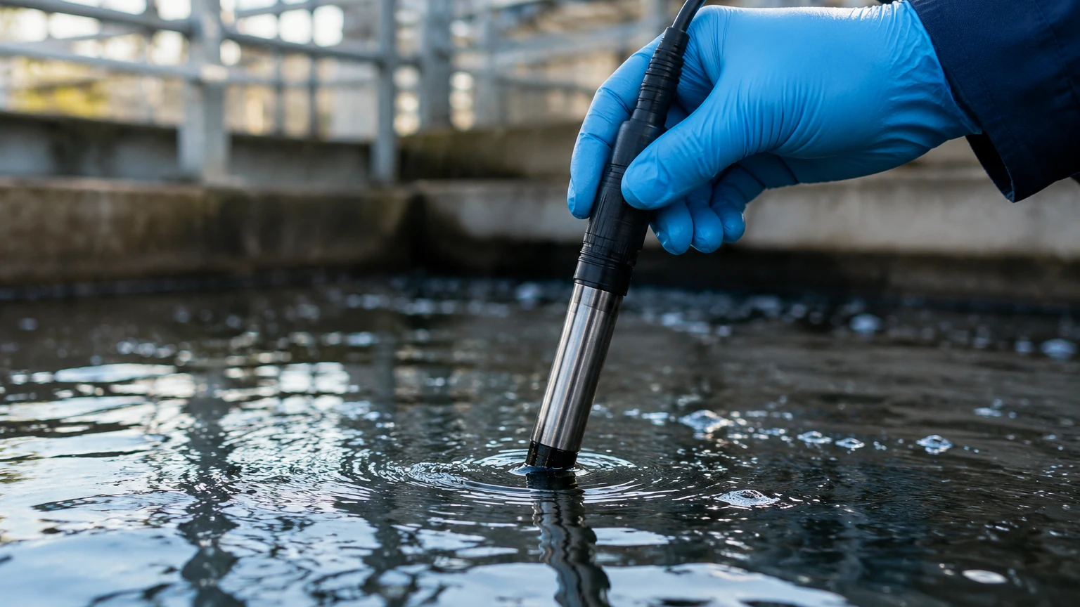
* Immersion Mounting: Used in open tanks or basins. The sensor is attached to an extension pipe and submerged. It is vital to ensure the cable entry is sealed against moisture.
* In-line Mounting: The sensor is placed directly into a process pipe using a T-fitting. This is common in high-pressure systems.
* Bypass (Flow Cell) Mounting: A small portion of the process fluid is diverted through a specialized chamber containing the sensor. This allows for maintenance and calibration without shutting down the main process line.
Electrical Considerations
ORP sensors produce a high-impedance signal. This means the signal is very weak and susceptible to electromagnetic interference (EMI).
1. Cable Length: Keep cables as short as possible. If the distance between the sensor and the transmitter exceeds 15 meters (approx. 50 feet), a pre-amplifier should be used.
2. Shielding: Use shielded coaxial cables and ensure they are not run parallel to high-voltage power lines or variable frequency drives (VFDs).
3. Ground Loops: Ensure the process liquid is properly grounded to prevent stray currents from affecting the mV reading.
Maintenance, Calibration, and Troubleshooting
Field ORP sensors are not "set and forget" instruments. They require periodic maintenance to ensure accuracy.
Cleaning Protocols
Fouling of the platinum tip is the most common cause of measurement drift.
* Oily/Greasy Deposits: Clean with a mild detergent and a soft brush.
* Mineral Scaling: Briefly soak in a 5% Hydrochloric Acid (HCl) solution.
* Protein Deposits: Use a solution of Pepsin in HCl.
Calibration (Verification)
Unlike pH sensors, ORP sensors cannot be "calibrated" in the sense of changing the slope of the electrode response. Instead, they are verified using ORP buffer solutions (e.g., +200 mV or +475 mV). If the sensor reading differs from the buffer value by more than ±30 mV, the sensor usually needs cleaning or replacement. Always allow the sensor to thermally equilibrate with the buffer solution before taking a reading.
Common Risks and Limitations
* Reference Poisoning: If the process contains ions that react with silver, the reference potential will shift, leading to permanent errors.
* Dry-out: If the sensor is left in a dry tank during a shutdown, the reference junction will dehydrate. Always keep the sensor tip wet, using a storage solution of 3M KCl if necessary.
* Slow Response: Often caused by a thin coating on the noble metal electrode. Lightly polishing the platinum tip with a very fine abrasive (like 600-grit alumina) can sometimes restore performance.
Integrating ORP Measurement with Level Control Systems
In modern industrial automation, the data from a field ORP sensor is rarely used in isolation. It is typically integrated with other process variables to provide a holistic view of the system.
For example, in a chemical batch reactor, a radar level meter (available via the Main Page) monitors the filling process. Once the desired volume is reached, the ORP sensor takes over to monitor the progress of the reaction. When the ORP reaches a specific setpoint (indicating the reaction is complete), the PLC (Programmable Logic Controller) triggers the discharge valve, and the level meter monitors the emptying process.
This synergy between physical measurement (level) and chemical measurement (ORP) allows for:
* Optimized Chemical Dosing: Reducing the waste of expensive oxidizers like ozone or peroxide.
* Safety Compliance: Ensuring that wastewater discharged into municipal sewers meets regulatory redox standards to prevent damage to infrastructure.
* Process Efficiency: Minimizing batch cycle times by accurately identifying the reaction endpoint.
Frequently Asked Questions (FAQ)
Q: How often should I calibrate my field ORP sensor?
A: In most industrial applications, a weekly verification is recommended. However, if the process is relatively clean, this may be extended to monthly. High-fouling environments may require daily cleaning.
Q: Can I use a pH transmitter for an ORP sensor?
A: Most modern analytical transmitters are dual-channel or selectable and can accept either pH or ORP inputs. However, you must ensure the transmitter is configured for the millivolt range rather than the pH scale.
Q: Why is my ORP reading drifting even after cleaning?
A: This is often a sign of a depleted reference electrolyte or a poisoned reference junction. If the sensor is a sealed "combination" type, the entire sensor must be replaced. If it is a refillable type, try replacing the internal electrolyte.
Q: Does ORP measure the concentration of chlorine?
A: Not directly. ORP measures the *effectiveness* of the chlorine. Factors like pH significantly affect how much of the chlorine is in its active (hypochlorous acid) form. Therefore, ORP is often used alongside pH measurement to provide a complete picture of disinfection power.
Q: What is the maximum distance for the sensor cable?
A: Without a pre-amplifier, the limit is generally 15 to 20 meters (approx. 50-65 feet). Beyond this, the high-impedance signal becomes too susceptible to noise and signal loss.
By following these engineering guidelines for selection, installation, and maintenance, industrial operators can ensure that their field ORP sensors provide the reliable data needed for precise chemical process control, complementing the physical monitoring provided by high-quality level measurement instrumentation.