Hydrostatic Level Transmitters
Hydrostatic Level Transmitters
Hydrostatic level measurement remains one of the most prevalent and reliable methods for monitoring liquid levels in industrial tanks, reservoirs, and open water bodies. By utilizing the physical relationship between the height of a liquid column and the pressure it exerts at its base, hydrostatic level transmitters provide a continuous signal that is easily integrated into automation systems. This guide explores the engineering principles, selection criteria, and installation best practices for these instruments, specifically tailored for engineers and plant managers in water treatment, chemical processing, and industrial automation.
Measurement Principles of Hydrostatic Pressure
The fundamental principle behind hydrostatic level transmitters is the measurement of the weight of a liquid column above a sensing element. According to the laws of fluid mechanics, the pressure at a specific depth in a static liquid is directly proportional to the height of the liquid above it. This relationship is expressed by the formula:
P = ρ · g · h
Where:
* P is the hydrostatic pressure (measured in Pascals or bar).
* ρ (rho) is the density of the liquid (kg/m³).
* g is the acceleration due to gravity (approximately 9.81 m/s²).
* h is the height of the liquid column (meters).
In practical industrial applications, since gravity is constant and the density of the liquid is usually known and relatively stable, the pressure measured by the transmitter is a direct indicator of the level. For example, in a water tank (density ≈ 1000 kg/m³), every 1 meter (3.28 ft) of water depth exerts approximately 0.098 bar (1.42 psi) of pressure.
Atmospheric Pressure Compensation
In open tanks or vented vessels, the sensor must account for changes in atmospheric pressure to ensure accuracy. If the ambient air pressure increases, it pushes down on the liquid surface, which would cause a standard pressure sensor to report a higher level than actually exists. To prevent this error, hydrostatic level transmitters typically use a vented cable or a reference port that allows the sensor to measure the "gauge pressure"—the difference between the liquid pressure and the current atmospheric pressure.
Types of Hydrostatic Level Transmitters
Depending on the application environment and tank geometry, hydrostatic sensors are generally categorized into two main physical configurations: submersible and externally mounted.
1. Submersible Level Transmitters
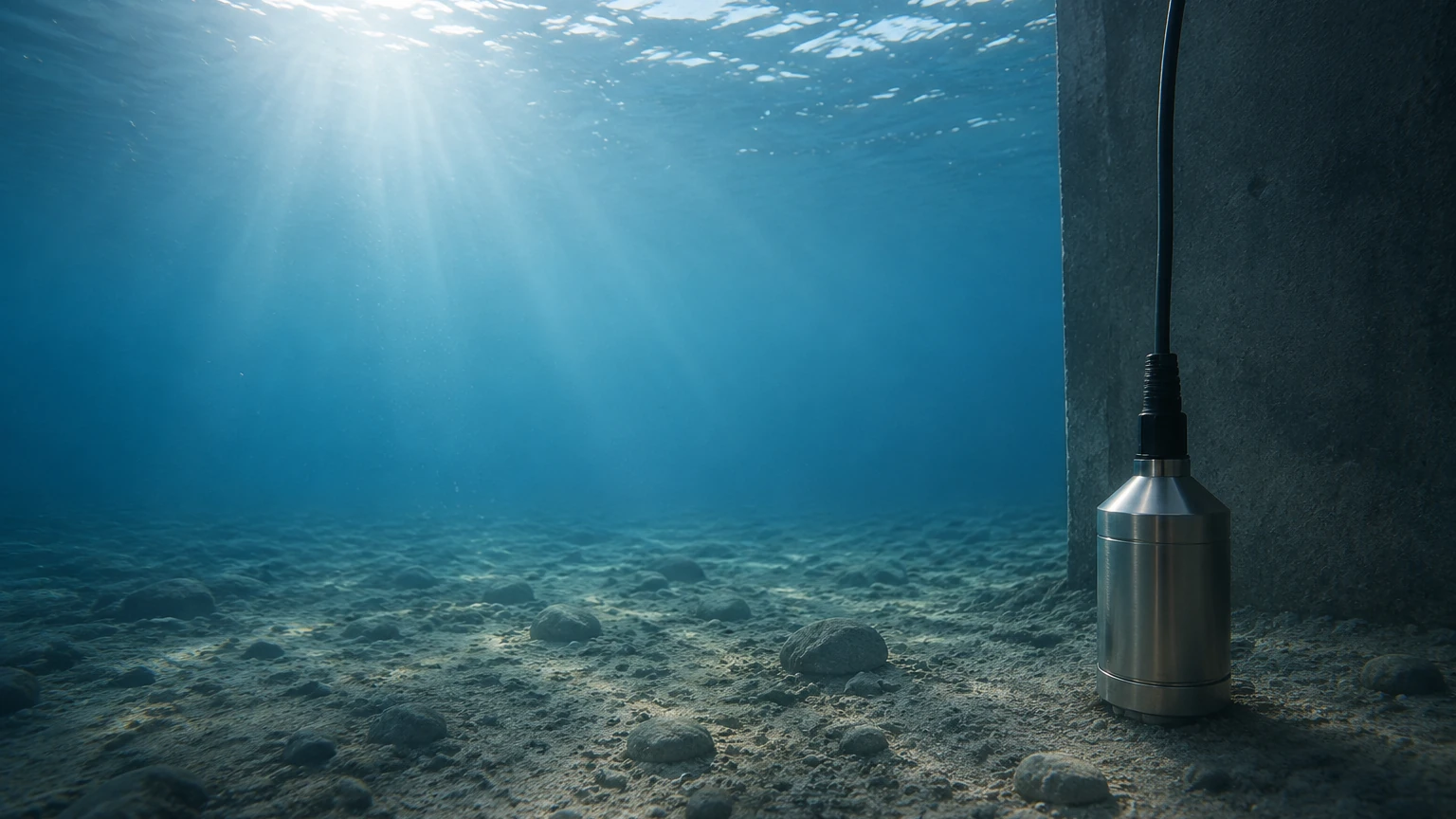
These are designed to be lowered directly into the liquid. The sensor is housed in a waterproof casing (often stainless steel or specialized plastics) and is suspended by a heavy-duty cable. This cable contains the electrical conductors and a small vent tube for atmospheric compensation.
* Best for: Deep wells, reservoirs, lift stations, and tanks where side-wall mounting is not possible.
* Advantages: Easy installation without tank modification; suitable for very deep measurements (up to 200m or more).
2. Externally Mounted (Tank-Side) Transmitters
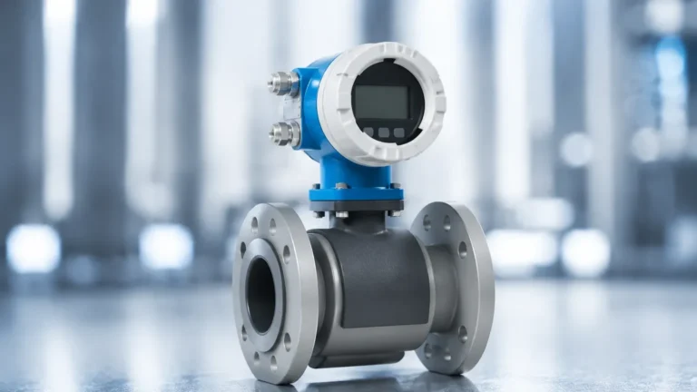
These transmitters are mounted to the outside of a tank via a flange or threaded connection at the lowest point of the vessel. The diaphragm of the sensor is in direct contact with the process fluid through the opening.
* Best for: Process tanks, chemical storage, and hygienic applications in the food or pharmaceutical industries.
* Advantages: Easier to maintain without removing the sensor from a deep well; can be isolated with valves for calibration.
Practical Selection Table
Choosing the right instrument requires balancing process conditions with sensor capabilities. The following table provides a comparison of common configurations offered by manufacturers like Welk.
| Feature | Submersible (Probe) | Externally Mounted (Flange/Thread) |
| :— | :— | :— |
| Typical Application | Water wells, wastewater pits | Chemical tanks, pressurized vessels |
| Installation Method | Suspended by cable | Bolted flange or NPT/G thread |
| Maintenance Access | Requires pulling the cable up | Accessible from tank exterior |
| Chemical Resistance | High (with PVDF/PTFE options) | High (with Alloy C/Tantalum diaphragms) |
| Pressure Compensation | Vented cable | Reference port or DP capillary |
| Max Temperature | Usually < 80°C (176°F) | Up to 150°C+ (302°F) with cooling |
Key Evaluation Criteria for Industrial Projects
When specifying hydrostatic level transmitters for a project, engineers must confirm several technical parameters to ensure long-term reliability.
Material Compatibility
The wetted parts, including the diaphragm and the housing, must be compatible with the process fluid. While 316L stainless steel is standard, aggressive chemicals like hydrochloric acid or sodium hypochlorite may require ceramic diaphragms or specialized coatings such as PTFE or PVDF. For seawater applications, titanium or Monel is often preferred to prevent pitting corrosion.
Density Variations
Because hydrostatic measurement relies on density (ρ), any significant change in liquid density will lead to measurement errors. If a tank stores different liquids at different times, or if the temperature fluctuates enough to change the density, the transmitter must be recalibrated, or the control system must apply a correction factor. For applications with highly variable densities, radar or ultrasonic sensors may be more appropriate.
Pressure Range and Overpressure Protection
The sensor's calibrated range should closely match the maximum height of the tank. However, it is also vital to check the "overpressure limit." In applications where pump surges or water hammer may occur, a sensor with a high overpressure rating is necessary to prevent permanent damage to the sensitive measuring diaphragm.
Installation Considerations and Best Practices
Proper installation is the most significant factor in the accuracy and lifespan of a hydrostatic level transmitter.
1. Venting and Moisture Protection: For submersible units, the vent tube in the cable must remain unobstructed. It is critical to use a bellows or a desiccant filter at the termination point to prevent moisture from entering the vent tube, which can lead to internal corrosion or sensor drift.
2. Avoiding Turbulence: Sensors should not be installed directly near an inlet pipe or an agitator. The kinetic energy of moving fluid can create localized pressure changes that the sensor will misinterpret as level fluctuations. If turbulence is unavoidable, a stilling well (a perforated pipe) should be used to shield the sensor.
3. Positioning: The sensor should be placed at least 50mm to 100mm (2 to 4 inches) above the bottom of the tank to prevent it from being buried in sediment or sludge, which can clog the diaphragm.
4. Cable Support: For deep submersible applications, the cable should be secured with a proper cable clamp to prevent stretching or damage over time due to the weight of the probe and cable.
Limitations and Common Risks
While hydrostatic level transmitters are versatile, they are not a "one-size-fits-all" solution. Understanding their limitations is key to successful engineering.
* Pressurized Tanks: In a sealed, pressurized tank, a standard hydrostatic transmitter will measure the sum of the liquid pressure and the gas blanket pressure. To measure only the liquid level, a Differential Pressure (DP) transmitter must be used, which subtracts the top-side gas pressure from the bottom-side total pressure.
* Build-up and Clogging: In wastewater or slurry applications, fats, oils, and grease (FOG) or solids can accumulate on the diaphragm. This increases the mass on the sensor or prevents it from moving, leading to false readings. Use of a flush-diaphragm or a large-diameter "clog-free" sensor is recommended in these cases.
* Density Sensitivity: As mentioned previously, if the liquid density changes by 5%, the level reading will also be off by 5%. This makes hydrostatic sensors less ideal for multi-product storage tanks without active density compensation.
Frequently Asked Questions (FAQs)
Q: Can hydrostatic level transmitters be used in boiling liquids?
A: It is challenging. Boiling liquids have significant density changes and turbulence. Furthermore, the steam can interfere with the atmospheric venting. External mounting with a cooling siphon or a different technology like guided wave radar is usually preferred.
Q: How often should these sensors be calibrated?
A: For standard water applications, an annual check is sufficient. In corrosive or high-precision chemical applications, a six-month calibration cycle is recommended to account for potential diaphragm fatigue or drift.
Q: Is the cable length of a submersible sensor adjustable?
A: Most manufacturers provide fixed lengths based on the order, but the cable can often be shortened in the field. However, lengthening the cable requires a specialized waterproof junction box to maintain the integrity of the vent tube.
Conclusion and Next Steps
Hydrostatic level transmitters offer a cost-effective and robust solution for many industrial level measurement challenges. By understanding the relationship between pressure and depth, and by carefully selecting materials and installation points, engineers can achieve high accuracy and low maintenance costs. For those looking to integrate these sensors into a broader process control strategy, it is essential to review the full range of available technologies.
To explore specific product specifications, technical data sheets, and customized OEM solutions for your next project, you can Review product options and application support on the Welk Main Page. Whether you are managing a municipal water project or a complex chemical plant, selecting the right instrument is the first step toward operational efficiency.