Clamp on Pressure Sensor
Clamp on Pressure Sensor
In the landscape of industrial process control, the demand for non-invasive measurement techniques has grown exponentially. Among these innovations, the clamp on pressure sensor stands out as a critical tool for facilities that prioritize system integrity, hygiene, and continuous operation. Unlike traditional invasive sensors that require pipe cutting, welding, or tapping, clamp-on technology allows for pressure monitoring from the exterior of the conduit. This article provides a comprehensive engineering reference for selecting, installing, and maintaining these sensors within B2B industrial environments.
Understanding the Measurement Principles
Before integrating a clamp on pressure sensor into a process loop, it is essential to understand the physics that allow external hardware to determine internal fluid conditions. Most industrial clamp-on sensors utilize one of two primary methodologies: strain-based measurement or ultrasonic transit-time analysis.
Strain-Based Measurement (Hoop Stress)
The most common principle for a clamp on pressure sensor involves measuring the minute mechanical deformation of the pipe wall. According to the principles of fluid mechanics and material science, internal pressure exerts a force against the inner walls of a pipe, causing it to expand. This expansion is known as "hoop stress."
The relationship between internal pressure ($P$), pipe diameter ($D$), and wall thickness ($t$) is defined by the hoop stress formula:
$$\sigma = \frac{PD}{2t}$$
High-precision strain gauges within the clamp-on housing detect these microscopic changes in the pipe's outer circumference. As the internal pressure rises, the pipe expands, and the strain gauge converts this physical displacement into an electrical signal (typically 4-20mA or a digital protocol like Modbus). This method is highly effective for metal pipes where the Young's Modulus of the material is well-defined and consistent.
Ultrasonic Correlation
Some advanced non-invasive sensors use ultrasonic waves to correlate pressure changes. While more commonly used for flow measurement, certain configurations analyze the change in the speed of sound through the fluid, which can be influenced by pressure-induced density changes. However, for most industrial applications involving water treatment or chemical processing, the strain-based approach remains the standard for clamp-on pressure monitoring.
Key Evaluation and Selection Criteria
Selecting the correct clamp on pressure sensor requires a detailed analysis of the existing piping infrastructure and the process media. Engineers must confirm several variables to ensure accuracy and long-term reliability.
Pipe Material and Condition
The effectiveness of a clamp-on sensor is directly tied to the pipe's ability to transmit strain.
* Metallic Pipes: Stainless steel, carbon steel, and copper are ideal candidates due to their predictable elastic deformation.
* Plastic/Composite Pipes: PVC, HDPE, and PEX pipes have much higher expansion rates and lower elastic moduli. Sensors must be specifically calibrated for these materials to avoid over-ranging the strain elements.
* Surface Integrity: The exterior of the pipe must be free of heavy corrosion, thick paint layers, or insulation. Any material between the sensor and the pipe wall can dampen the strain signal, leading to inaccurate readings.
Pressure Range and Sensitivity
Clamp-on sensors are generally less sensitive to very low-pressure fluctuations than invasive diaphragm sensors. They excel in high-pressure environments where the pipe expansion is more pronounced. When reviewing product options, engineers should verify the "Minimum Detectable Pressure Change" for their specific pipe schedule.
Temperature Considerations
Thermal expansion can be mistaken for pressure-induced strain. High-quality sensors include integrated temperature compensation. This involves a secondary sensor that measures the pipe wall temperature, allowing the internal processor to subtract the thermal expansion component from the total strain measured.
| Feature | Specification Detail | Industrial Relevance |
| :— | :— | :— |
| Measurement Range | 0 to 100 bar (typical) | Suitable for most pump discharge lines |
| Accuracy | ±1% to ±3% of Full Scale | Sufficient for monitoring and protection |
| Operating Temp | -20°C to +120°C | Covers water and most chemical processes |
| Output Signal | 4-20mA, RS485, HART | Integration with PLC/SCADA systems |
| Enclosure Rating | IP67 or IP68 | Protection against washdowns and outdoor use |
Practical Selection Table for Industrial Applications
When planning a deployment, use the following table to align sensor types with specific application needs:
| Application Type | Preferred Sensor Tech | Key Requirement |
| :— | :— | :— |
| High-Purity Chemicals | Strain-based Clamp-on | Zero contamination risk (No wetted parts) |
| Slurry/Abrasive Fluids | Heavy-duty Clamp-on | Avoids sensor erosion from grit |
| Temporary Auditing | Portable Clamp-on | Ease of installation/removal |
| High-Pressure Hydraulics | Precision Strain-Gauge | High fatigue resistance of the clamp |
| Water Distribution | Battery-powered Wireless | Remote monitoring without cabling |
For more detailed technical specifications and to explore a wider range of industrial measurement tools, you may visit the Main Page for comprehensive product support.
Installation Considerations and Best Practices
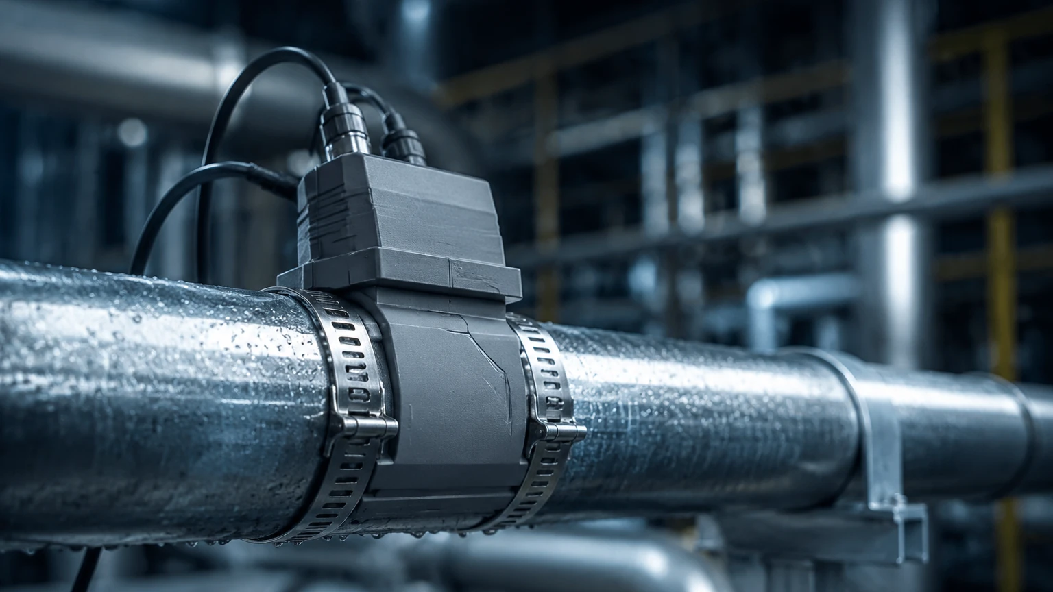
The performance of a clamp on pressure sensor is heavily dependent on the quality of the installation. Unlike a threaded sensor that simply needs to be tightened into a port, a clamp-on unit requires precise mechanical coupling.
1. Surface Preparation
The contact area on the pipe must be cleaned down to the bare material. For steel pipes, this often involves using a wire brush or sandpaper to remove rust and scale. A smooth surface ensures that the strain is transmitted directly to the sensor's sensing element without loss.
2. Mounting Location
Avoid installing sensors near elbows, valves, or pumps where turbulent flow can cause localized pressure fluctuations or mechanical vibration. A rule of thumb is to install the sensor on a straight run of pipe at least five pipe diameters away from any disturbance.
3. Coupling Agents
In many designs, a specialized acoustic or mechanical coupling grease is applied between the sensor face and the pipe. This grease fills microscopic voids and ensures a continuous path for the physical forces to travel. Over time, this grease can dry out in high-temperature applications, necessitating a periodic maintenance check.
4. Zeroing and Calibration
Once the sensor is clamped onto the pipe, it must be "zeroed." This is ideally done when the pipe is at atmospheric pressure (empty or vented). If the pipe cannot be depressurized, many modern sensors allow for a "live zeroing" based on a known reference pressure provided by a portable master gauge.
Limitations and Common Risks
While the clamp on pressure sensor offers significant advantages, engineers must be aware of its factual boundaries and limitations:
* Wall Thickness Sensitivity: On extremely thick-walled pipes (e.g., Schedule 160), the internal pressure may not produce enough external strain for the sensor to detect accurately. Conversely, on very thin-walled pipes, the pressure might cause deformation that exceeds the sensor's elastic limit.
* Material Creep: In plastic piping systems, the material may exhibit "creep" over time under constant pressure, which can lead to a baseline shift in the sensor's output.
* Vibration Interference: High-frequency vibrations from nearby machinery can introduce noise into the strain signal. Using damped mounting brackets or digital filtering in the PLC can mitigate this, but it remains a factor in heavy industrial zones.
* Not for Vacuum: Most clamp-on pressure sensors are designed to measure positive pressure (expansion). They are generally not suitable for vacuum applications where the pipe might contract slightly, as the mechanical coupling is optimized for expansion.
Relationship to Level Measurement
In the context of the Welk product ecosystem, pressure measurement is often the foundation for hydrostatic level sensing. While many level applications use submersible or externally mounted threaded transmitters, a clamp on pressure sensor can be used in specific tank-bottom piping scenarios to estimate the head pressure of a liquid column. This is particularly useful in chemical tanks where the media is too aggressive for any wetted material, or where the tank lacks a bottom discharge port suitable for a traditional transmitter. By measuring the pressure at the lowest point of the discharge pipe, the system can calculate the liquid level based on the fluid's density.
Frequently Asked Questions (FAQs)
Q: Can a clamp on pressure sensor be used on lined pipes?
A: It depends on the lining. If the lining (like PTFE or rubber) is tightly bonded to the pipe wall, the strain may still transmit. However, if there is an air gap or a loose sleeve, the sensor will not receive an accurate strain signal. Generally, lined pipes are not recommended for this technology unless specifically tested.
Q: How often does the sensor require recalibration?
A: For most stable industrial environments, an annual calibration check is sufficient. However, in applications with high thermal cycling, semi-annual checks are recommended to ensure the temperature compensation remains accurate.
Q: Does the fluid type affect the reading?
A: Indirectly, yes. The sensor measures the pipe's reaction to pressure, so the fluid's density or viscosity doesn't change the mechanical strain. However, the fluid's temperature will affect the pipe wall, which must be compensated for.
Q: Is it possible to move the sensor from one pipe to another?
A: Yes, one of the primary benefits is portability. However, the sensor must be re-calibrated for the new pipe's material, diameter, and wall thickness to provide accurate data.
Conclusion
The clamp on pressure sensor represents a sophisticated intersection of mechanical engineering and electronic sensing. By leveraging the predictable expansion of industrial piping, these devices provide a safe, clean, and efficient way to monitor system pressure without the risks associated with traditional invasive mounting. When selected with a clear understanding of pipe metallurgy and installed with attention to surface preparation, they offer a reliable solution for modern process automation. For engineers looking to integrate these or other level and pressure measurement technologies, it is advisable to Review product options and application support to ensure the selected hardware meets the specific demands of the operating environment.