Dl10
Dl10
In the field of industrial automation and process control, the DL10 series represents a standard for compact, non-contact ultrasonic level measurement. Designed primarily for short-range applications in small to medium-sized tanks, the dl10 provides a reliable solution for monitoring liquids without coming into direct contact with the medium. This guide explores the technical foundations, application engineering, and selection criteria for utilizing these sensors within modern industrial frameworks.
As a professional manufacturer of industrial level measurement instruments, Welk provides a comprehensive range of solutions, including radar level meters, ultrasonic sensors, and hydrostatic transmitters. For engineers seeking detailed specifications or customized OEM services, visiting the Main Page offers access to a full suite of technical documentation and product support.
Understanding Ultrasonic Level Measurement Principles
The dl10 operates on the "Time-of-Flight" (ToF) principle. This method relies on the physics of sound waves and their behavior when transitioning between different media.
The Transducer Mechanism
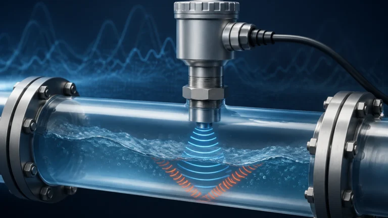
Inside the sensor housing, a piezoelectric crystal acts as both a transmitter and a receiver. When energized, the crystal vibrates at a specific ultrasonic frequency (typically between 40 kHz and 70 kHz for this class of device). This vibration generates a pulse of sound that travels through the air toward the surface of the liquid.
Distance Calculation
Upon hitting the liquid surface, the sound pulse is reflected back to the sensor. The dl10 electronics measure the exact time interval between the emission of the pulse and the reception of the echo. The distance is calculated using the formula:
Distance = (Speed of Sound × Time) / 2
The speed of sound in air is approximately 343 meters per second at 20°C. However, because the speed of sound varies with air temperature, high-quality sensors like those in the dl10 category include an integrated temperature sensor to provide automatic compensation, ensuring accuracy across varying ambient conditions.
Technical Specifications of the DL10 Series
The dl10 is characterized by its compact form factor and integrated electronics, making it an "all-in-one" transmitter. Unlike larger industrial units that require separate control modules, these sensors output a direct signal to a PLC or SCADA system.
Key Performance Metrics
* Measurement Range: Typically optimized for 1.25 meters (49.2 inches) to 10 meters (32.8 feet).
* Accuracy: Generally ±0.25% of the detected span in air.
* Output Signal: Standard 4-20 mA analog output, often with a two-wire loop-powered configuration.
* Beam Angle: Narrow beam angles (often between 8° and 12°) to minimize interference from tank walls or internal obstructions.
* Dead Band: A critical specification, usually ranging from 50 mm to 200 mm, where the sensor cannot accurately measure because the pulse has not yet finished transmitting before the echo returns.
Material Construction
To withstand corrosive environments, the wetted parts are typically constructed from chemically resistant plastics. Polyvinylidene fluoride (PVDF) is a common choice for the transducer face, while the housing may be Polypropylene (PP) or Type 6 Nylon. This allows the dl10 to be used with acids, bases, and various aqueous solutions.
Application Suitability and Industry Use Cases
The dl10 is a versatile tool across multiple sectors, provided the environmental conditions align with ultrasonic physics.
Water and Wastewater Treatment
In municipal water treatment, these sensors are frequently used for monitoring chemical feed tanks (such as sodium hypochlorite or alum). Their non-contact nature prevents the corrosive fumes from degrading the sensor elements, a common failure point for contact-based hydrostatic probes.
Chemical Processing
For small-scale chemical storage, the dl10 provides a cost-effective alternative to expensive radar units. It is particularly effective in atmospheric tanks where the pressure remains stable and the liquid surface is relatively calm.
Industrial Automation and OEM Integration
Because of its small footprint and standard mounting threads (often 1" or 2" NPT/G), the dl10 is easily integrated into skid-mounted systems, such as cooling towers, lubricant reservoirs, and hydraulic power units.
Comparative Selection: DL10 vs. Alternative Technologies
Selecting the right level measurement technology requires balancing cost, accuracy, and environmental constraints. The following table compares the dl10 (ultrasonic) with other common technologies available through the Main Page of industrial suppliers.
| Feature | Ultrasonic (DL10) | Radar (80GHz) | Hydrostatic | Magnetic Gauge |
| :— | :— | :— | :— | :— |
| Measurement Type | Non-contact | Non-contact | Contact (Pressure) | Contact (Visual/Float) |
| Typical Range | 0.1m – 10m | 0.1m – 120m | 1m – 200m | 0.3m – 6m |
| Accuracy | High (in stable air) | Very High | Medium | High |
| Vapor Sensitivity | High | Low | None | None |
| Foam Resistance | Poor | Moderate | Excellent | Excellent |
| Relative Cost | Low | High | Medium | Medium-High |
When to Choose the DL10
The dl10 is the preferred choice when the budget is a primary concern and the application involves clean, non-foaming liquids in atmospheric tanks. If the application involves heavy steam, high pressure, or vacuum conditions, a radar level meter or a magnetic level gauge would be more appropriate.

Installation Best Practices and Configuration
Proper installation is the most significant factor in the long-term reliability of a dl10 sensor. Engineers must follow specific geometric guidelines to ensure a clear signal path.
Mounting Position
1. Vertical Alignment: The sensor must be mounted perfectly perpendicular to the liquid surface. A tilt of even a few degrees can cause the reflected signal to miss the receiver, leading to a "Loss of Echo" (LOE) error.
2. Wall Clearance: The sensor should be placed at least 10% of the tank height away from the side walls. This prevents the ultrasonic beam from hitting the wall and creating false echoes.
3. Obstruction Avoidance: Ensure the beam path is clear of ladders, pipes, or agitators. If obstructions are unavoidable, many dl10 units allow for "False Echo Suppression" via software configuration to ignore these static reflections.
Dealing with the Dead Band
The sensor must be mounted high enough so that the maximum liquid level never enters the dead band (blanking distance). If the liquid reaches the transducer face, the sensor will typically output a maximum or minimum error signal, as it cannot process the return pulse.
Environmental Shielding
While many dl10 sensors are rated IP67 or IP68, they should be shielded from direct sunlight in outdoor installations. Rapid temperature changes on the sensor body can lead to condensation on the transducer face, which may temporarily block the ultrasonic signal.
Overcoming Operational Limitations and Environmental Factors
Ultrasonic technology has inherent limitations that must be understood during the engineering phase.
The Impact of Foam
Foam is the primary enemy of ultrasonic sensors. Because foam is composed of air bubbles with very little mass, it absorbs the sound energy rather than reflecting it. If a tank develops a thick layer of foam, the dl10 may lose its signal entirely. In such cases, a stilling well can sometimes be used to provide a clear liquid surface for the sensor.
Vacuum and Pressure
Sound requires a medium (air or gas) to travel. In a vacuum, the dl10 cannot function. Similarly, in high-pressure environments, the change in air density alters the speed of sound significantly, often beyond the compensation limits of the internal software. Most dl10 units are rated for atmospheric pressure or very low positive pressure (up to 0.5 bar).
Vapor and Dust
Heavy vapors (such as those from solvents) can change the composition of the air in the tank, affecting the speed of sound and causing measurement errors. Likewise, heavy dust in the air can scatter the ultrasonic pulse. For these environments, non-contact radar is usually the recommended alternative.
Maintenance, Calibration, and Troubleshooting
One of the main advantages of the dl10 is its low maintenance requirement due to the lack of moving parts. However, periodic checks are necessary.
Cleaning the Transducer
In applications where splashing occurs, the transducer face may accumulate residue. This should be cleaned with a soft cloth and mild detergent. Abrasive cleaners or sharp tools should never be used, as they can damage the delicate piezoelectric interface.
Signal Troubleshooting
* Intermittent Signal: Often caused by turbulence or agitator blades. Increasing the damping or response time in the sensor settings can smooth out the output.
* Fixed Output (20mA or 4mA): This usually indicates a Loss of Echo. Check for foam, excessive vapor, or whether the liquid has entered the dead band.
* Inaccurate Readings: Verify the temperature compensation is working and ensure the sensor is mounted level. If the error is consistent, recalibrate the 4mA (empty) and 20mA (full) points.
Frequently Asked Questions (FAQ)
Q: Can the dl10 be used to measure dry solids like grain or sand?
A: While some ultrasonic sensors are designed for solids, the dl10 is typically optimized for liquids. Solids have an uneven surface that scatters the sound pulse, and dust can interfere with the signal. For solids, a high-power radar or a specialized solids ultrasonic transmitter is preferred.
Q: What is the maximum cable length for a dl10 sensor?
A: Since most dl10 units use a 4-20 mA current loop, the cable length can extend up to several hundred meters, depending on the power supply voltage and the resistance of the wire. Typically, 300 to 500 meters is achievable with standard twisted-pair shielded cable.
Q: Does the dl10 require a specific software for configuration?
A: Many modern dl10 units can be configured via an integrated display and push-buttons, while others use a USB or Bluetooth interface with a proprietary app or FDT/DTM software. Always check the specific model's documentation for configuration requirements.
For further technical assistance or to explore a wide range of industrial level measurement hardware, please refer to the Main Page for expert guidance and product selection tools.