Water Level Controls
Water Level Controls
In industrial environments, water level controls are fundamental components that ensure the safety, efficiency, and continuity of processes. From municipal wastewater treatment and chemical processing to cooling towers in power plants, the ability to monitor and regulate liquid levels prevents equipment damage, reduces waste, and maintains product quality. Selecting the appropriate control system requires a deep understanding of the underlying measurement technologies, the physical properties of the medium, and the specific constraints of the installation site.
Effective water level controls transition a system from manual oversight to automated precision. This guide explores the engineering principles behind modern level measurement, provides a framework for technology selection, and addresses the practical challenges encountered in industrial applications.
Measurement Principles and Technologies
Before implementing a control strategy, it is essential to understand how different instruments perceive the liquid surface. Industrial water level controls generally fall into two categories: continuous level measurement and point level detection.
Radar Level Measurement (Non-Contact)
Radar level meters operate on the Time-of-Flight (ToF) principle. The sensor emits high-frequency microwave pulses (typically in the 26 GHz or 80 GHz range) that travel at the speed of light. When these pulses hit the water surface, they are reflected back to the sensor. The device calculates the distance based on the time interval between transmission and reception.
* Advantages: Radar is unaffected by temperature fluctuations, pressure changes, or the presence of dust and vapors. High-frequency 80 GHz radar offers a narrow beam angle, making it ideal for tall, narrow tanks or vessels with internal obstructions.
* Limitations: The dielectric constant of the liquid affects signal reflection. While water has a high dielectric constant (approx. 80), foam on the surface can sometimes scatter the signal.
Ultrasonic Level Sensors (Non-Contact)
Similar to radar, ultrasonic sensors use the ToF principle but utilize sound waves instead of microwaves. The sensor emits an ultrasonic pulse that reflects off the liquid surface.
* Advantages: Highly cost-effective for open-channel flow and standard atmospheric tanks. It is a preferred choice for water treatment sumps and irrigation channels.
* Limitations: Because sound requires a medium to travel, ultrasonic sensors are sensitive to air temperature, turbulence, and heavy foam. They cannot be used in vacuum conditions.
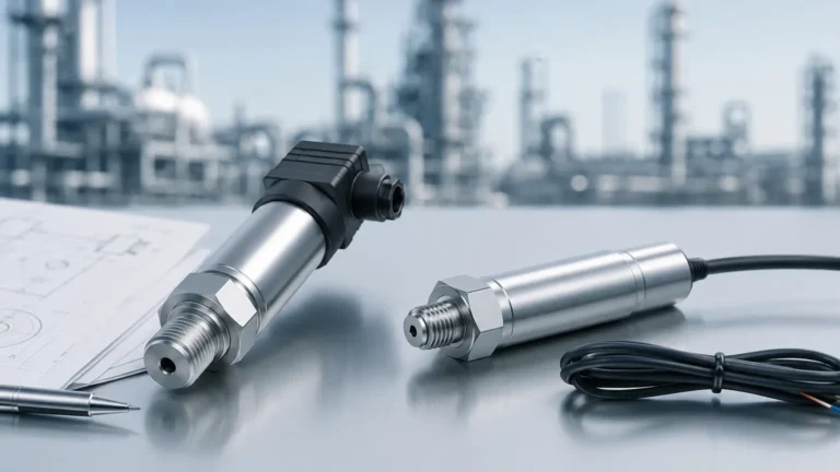
Hydrostatic Level Transmitters (Contact)
Hydrostatic measurement relies on the relationship between the height of a liquid column and the pressure it exerts at the base. The formula $P = \rho gh$ (where $P$ is pressure, $\rho$ is density, $g$ is gravity, and $h$ is height) allows the transmitter to determine the level based on the weight of the water above the sensor.
* Advantages: Simple to install (often submersible) and highly reliable for deep wells, reservoirs, and vented tanks.
* Limitations: Changes in liquid density (due to temperature or concentration shifts) will affect accuracy. The sensor must be in contact with the liquid, which may require specific material compatibility for treated water.
Magnetic Level Gauges (Contact)
These devices use a float containing a magnet that moves with the water level inside a bypass chamber. Outside the chamber, magnetic flaps or a follower indicate the level visually, while a reed chain or transmitter can provide an electronic signal.
* Advantages: Provides a clear visual indication without requiring power. It is excellent for high-pressure or high-temperature boiler water applications.
* Limitations: Mechanical floats can become stuck if the water contains high levels of particulates or scaling minerals.
Selection Criteria for Industrial Applications
Choosing the right water level controls involves more than just matching a sensor to a tank. Engineers must evaluate the application against several technical parameters to ensure long-term reliability.
1. Media Characteristics: Is the water pure, or does it contain chemicals, solids, or biological matter? Corrosive additives in chemical water treatment require PVDF or PTFE-coated sensors, while wastewater with high solids may favor non-contact radar to avoid clogging.
2. Process Conditions: Consider the operating temperature and pressure. Hydrostatic sensors are excellent for atmospheric tanks, but pressurized vessels often require guided wave radar or differential pressure transmitters.
3. Measurement Range: For shallow tanks (under 2 meters), ultrasonic or small radar units are efficient. For deep boreholes exceeding 100 meters, submersible hydrostatic transmitters are typically the most practical solution.
4. Accuracy Requirements: Billing and custody transfer applications require high-precision radar (error < 2mm), whereas simple pump control in a sump might only require an accuracy of ±1% of the span.
Practical Selection Table
| Technology | Best Application | Max Range (Typical) | Accuracy | Maintenance Level |
| :— | :— | :— | :— | :— |
| Radar (80 GHz) | Narrow tanks, agitated liquids | Up to 120m | ±1-2 mm | Low (Non-contact) |
| Ultrasonic | Open channels, sumps | Up to 15m | ±0.25% | Moderate (Clean sensor face) |
| Hydrostatic | Deep wells, reservoirs | Up to 500m | ±0.1-0.5% | Low (Check for scaling) |
| Magnetic Gauge | Boilers, pressurized tanks | Up to 6m | ±5-10 mm | Moderate (Mechanical) |
| Level Switch | Overflow/Run-dry protection | N/A | N/A | Low |
Installation Considerations and Best Practices
Proper installation is as critical as technology selection. Even the most advanced water level controls will fail if positioned incorrectly.
* Dead Zones (Blocking Distance): Both radar and ultrasonic sensors have a "dead zone" directly beneath the transducer where measurements cannot be taken. Ensure the sensor is mounted high enough so that the maximum water level never enters this zone.
* Mounting Position: Sensors should generally be mounted away from the tank wall to avoid false reflections (for radar/ultrasonic) and away from the fill inlet to avoid turbulence and air entrainment.
* Stilling Wells: In tanks with heavy agitation or surface foam, installing the sensor inside a stilling well (a vertical pipe) can provide a calm surface for more accurate measurement.
* Venting: For hydrostatic sensors, a vented cable is necessary to compensate for changes in atmospheric pressure. Ensure the vent tube is protected by a desiccant filter to prevent moisture ingress, which can lead to sensor drift.
Common Risks and Limitations
While modern instrumentation is robust, certain environmental factors can introduce risks to the control loop:
* Signal Interference: In metal tanks, internal structures like ladders or agitator blades can cause "ghost echoes" for radar and ultrasonic units. Most modern controllers offer "false signal suppression" to map out these obstructions.
* Vapor and Condensation: In high-temperature water applications, steam and condensation can build up on the sensor face. Some radar units feature drip-off lens designs to mitigate this, while ultrasonic units may struggle as the speed of sound changes in steam-saturated air.
* Build-up and Scaling: In hard water or wastewater applications, calcium carbonate or biological film can build up on contact-type sensors. Regular inspection schedules are necessary to ensure that floats move freely and diaphragms are not coated.
For a comprehensive overview of available technologies and detailed specifications, engineers can visit the Main Page to review product options and application support.
Project Confirmation Checklist
Before finalizing a purchase or design for water level controls, project managers should confirm the following details:
1. Tank Geometry: Provide the height, diameter, and shape of the tank bottom (flat, conical, or dished).
2. Mounting Type: Determine if the connection will be threaded (e.g., G1½, NPT), flanged (ANSI or DIN), or bracket-mounted for open water.
3. Output Requirements: Specify the communication protocol required for the PLC or SCADA system (e.g., 4-20mA, HART, Modbus RS485, or Profibus).
4. Power Supply: Confirm available power (24V DC is standard for loop-powered sensors, while some radar units may require 220V AC).
5. Environmental Rating: Ensure the sensor meets the required IP rating (IP68 for submersion) and any necessary hazardous area certifications (ATEX/IECEx) if flammable vapors are present.
Frequently Asked Questions (FAQs)
Q: Can I use one sensor for both level control and flow measurement?
A: Yes, in open channels (like flumes or weirs), ultrasonic and radar sensors can calculate flow rates based on the water level using pre-programmed flow formulas.
Q: How do I handle water level controls in freezing environments?
A: For outdoor reservoirs, hydrostatic sensors are often placed below the frost line. For non-contact sensors, heaters can be integrated into the housing to prevent ice formation on the transducer face.
Q: What is the difference between a level transmitter and a level switch?
A: A level transmitter provides continuous measurement (e.g., 0-100%), allowing for precise control. A level switch is a point-level device that provides a simple on/off signal when a specific level is reached, typically used for high-level alarms or pump start/stop logic.
Q: Is radar always better than ultrasonic?
A: Not necessarily. While radar is more versatile in complex environments, ultrasonic sensors remain a highly effective and lower-cost solution for simple water applications under atmospheric pressure where foam and steam are not present.
By carefully matching the measurement principle to the specific needs of the facility, operators can implement water level controls that provide years of maintenance-free service and ensure the integrity of the industrial process.