Radar Lv
Radar Lv
In the landscape of industrial process control, the term "radar lv" refers to the sophisticated application of radar technology for level measurement. As industries move toward greater automation and higher precision requirements, radar level transmitters have become the benchmark for reliability in challenging environments. Whether dealing with corrosive chemicals, high-temperature molten materials, or volatile hydrocarbons, understanding the nuances of radar level (LV) systems is essential for process engineers and plant managers.
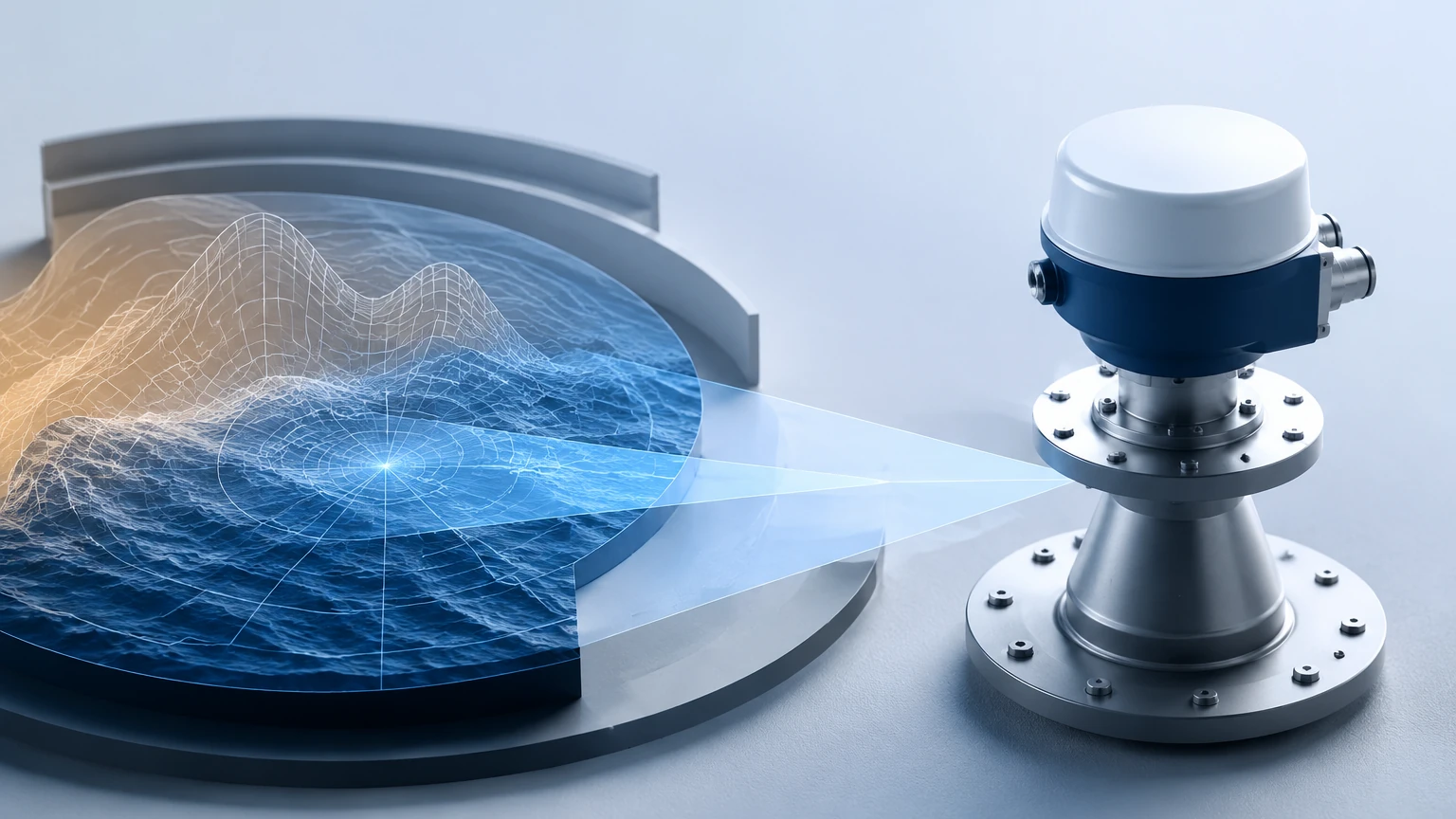
At its core, radar level measurement is a top-down, time-of-flight technology. It involves the emission of electromagnetic waves toward a target medium, which then reflects these waves back to a receiver. By calculating the time elapsed or the frequency shift between emission and reception, the instrument determines the exact distance to the product surface. This data is then converted into a level or volume reading, providing critical input for inventory management and process safety.
Measurement Principles of Radar LV Technology
To select the correct instrument, one must first understand the two primary methods used in modern radar level sensing: Pulse Radar and Frequency Modulated Continuous Wave (FMCW).
Pulse Radar (Time of Flight)
Pulse radar transmitters emit high-frequency microwave pulses (typically in the 6 GHz or 26 GHz range). These pulses travel at the speed of light, hit the surface of the medium, and bounce back. The sensor measures the time it takes for the pulse to complete the round trip. Since the speed of light is constant, the distance is easily calculated. Pulse radar is known for its energy efficiency and is often used in battery-powered or loop-powered applications where power consumption is a concern.
Frequency Modulated Continuous Wave (FMCW)
FMCW radar technology is often preferred for high-precision industrial applications. Instead of sending discrete pulses, the transmitter emits a continuous signal with a constantly changing frequency (a frequency sweep). When the reflected signal is received, it is compared to the signal being emitted at that exact moment. The difference in frequency is directly proportional to the distance. FMCW radar, particularly at higher frequencies like 80 GHz, offers superior resolution and signal-to-noise ratios, making it ideal for measuring narrow tanks or materials with low dielectric constants.
Guided Wave vs. Non-Contact Radar
Radar LV instruments are categorized into two physical configurations based on how the microwave signal is transmitted to the medium.
Non-Contact Radar
Non-contact radar transmitters are mounted at the top of a vessel and emit signals through the air. This is the preferred method for hygienic applications, corrosive media that might damage a probe, or processes where the medium is agitated. Because there is no physical contact with the material, maintenance requirements are significantly reduced. Modern 80 GHz radar units have a very narrow beam angle, which allows them to avoid internal tank obstructions like agitators or heating coils.
Guided Wave Radar (GWR)
Guided Wave Radar utilizes a physical probe (cable or rod) to guide the microwave signal directly to the surface. This method is highly effective for liquids with low dielectric constants (such as oils or liquefied gases) because the probe concentrates the energy of the signal. GWR is also unaffected by surface turbulence, foam, or heavy steam, which can sometimes scatter the signals of non-contact radar. However, because the probe is immersed in the medium, material compatibility and mechanical stress on the probe must be considered.
Selection Criteria for Radar LV Systems
Choosing the right radar level transmitter requires a detailed analysis of the process conditions. The following table provides a general comparison to assist in the initial selection phase.
| Feature | Pulse Radar (26 GHz) | FMCW Radar (80 GHz) | Guided Wave Radar (GWR) |
| :— | :— | :— | :— |
| Best Application | General liquid storage | Narrow tanks, solids, high precision | Low dielectric liquids, interface |
| Accuracy | ±3 mm to ±10 mm | ±1 mm to ±2 mm | ±2 mm to ±5 mm |
| Maximum Range | Up to 30 meters | Up to 120 meters | Up to 75 meters |
| Beam Angle | Wide (approx. 10°-20°) | Narrow (approx. 3°-8°) | N/A (signal follows probe) |
| Surface Conditions | Calm liquids | Calm to moderately turbulent | Highly turbulent, foam, steam |
| Dielectric Constant | > 1.9 | > 1.4 | > 1.2 (or lower with coax) |
Practical Installation Considerations
Even the most advanced radar LV instrument will fail to perform accurately if installed incorrectly. Engineers should adhere to the following guidelines during the design and installation phase:
1. Nozzle Height and Diameter: The mounting nozzle should be as short as possible. If the nozzle is too long or narrow, it can create internal reflections (ringing) that interfere with the signal near the top of the tank, creating a "dead zone."
2. Obstruction Clearance: For non-contact radar, the signal spreads in a cone shape. It is vital to ensure that this cone does not intersect with tank walls, ladders, or agitators. If an obstruction is unavoidable, software-based "false echo suppression" can be used to map out these static reflections.
3. Positioning: Radar units should never be mounted in the center of a domed tank, as the dome can act as a parabolic reflector and concentrate noise. Ideally, the unit should be placed at 1/3 of the tank radius from the wall.
4. Inlet Flow: Avoid installing the sensor directly above the material inlet. The turbulence and splashing from the incoming flow will create significant signal noise and potential false readings.
Limitations and Environmental Factors
While radar is highly versatile, it is not a universal solution. Certain physical properties can limit its effectiveness:
* Dielectric Constant (εr): The reflectivity of a material depends on its dielectric constant. Water has a high εr (~80) and is easy to measure. Hydrocarbons often have a low εr (<2), which reflects less energy. In these cases, GWR or high-frequency FMCW is necessary.
* Heavy Foam: Dense, thick foam can absorb radar signals entirely, leading to a loss of signal. While GWR can sometimes penetrate foam to find the liquid level, non-contact radar may only see the top of the foam or fail to return a signal.
* Dust and Condensation: While radar can typically penetrate dust better than ultrasonic sensors, extremely heavy dust in solids silos can attenuate the signal. Similarly, heavy condensation on the antenna lens can cause signal scattering, though many modern units use PTFE drop antennas to shed moisture.
Maintenance and Troubleshooting
Radar LV instruments are generally low-maintenance due to their solid-state electronics and lack of moving parts. However, periodic checks are recommended:
* Signal Strength Monitoring: Most digital radar transmitters provide a "signal quality" or "echo margin" metric. A declining signal strength over time may indicate buildup on the antenna or probe.
* Cleaning: In applications with crystallizing liquids or sticky resins, the antenna or GWR probe may require periodic cleaning to prevent measurement drift.
* Verification: Periodic manual gauging (dip tape) should be performed to verify the transmitter's calibration, especially in custody transfer applications.
For comprehensive technical support and a wide range of industrial measurement solutions, including radar, ultrasonic, and hydrostatic sensors, professionals are encouraged to visit the Main Page for detailed product specifications and application engineering assistance.
Frequently Asked Questions (FAQs)
Q: Can radar LV be used in vacuum tanks?
A: Yes. Unlike ultrasonic sensors, which require a medium (air) to transmit sound, radar uses electromagnetic waves that travel freely through a vacuum. This makes radar the ideal choice for vacuum distillation columns and similar vessels.
Q: How does temperature affect radar accuracy?
A: Radar is largely unaffected by temperature changes in the vapor space because the speed of light is constant. However, extreme temperatures can affect the electronics or the mechanical seals of the instrument. Always check the operating temperature limits of the specific model (e.g., -40°C to +250°C).
Q: Is radar suitable for measuring solids?
A: Yes, but it requires careful selection. Solids like grain, plastic pellets, or cement have uneven surfaces that scatter signals. High-frequency FMCW radar (80 GHz) is typically used for solids because its narrow beam can be aimed more precisely and its high dynamic range can process weak reflections from sloped surfaces.
Q: What is the "Dead Zone" in radar measurement?
A: The dead zone (or blocking distance) is the area immediately below the sensor where it cannot accurately measure. This is usually due to the time required for the electronics to switch from transmit to receive mode. In GWR, the dead zone is also influenced by the transition from the housing to the probe.
By carefully evaluating the dielectric properties of the media, the physical constraints of the vessel, and the required precision, engineers can implement radar LV solutions that provide years of maintenance-free service. For more information on selecting the right technology for your specific industry, refer to the resources available on the Main Page.