Device to Check Oil Level in Tank
Device to Check Oil Level in Tank
In industrial environments, selecting the appropriate device to check oil level in tank systems is a critical decision that impacts operational safety, inventory management, and process efficiency. Oil, whether it is crude, refined fuel, lubricant, or hydraulic fluid, presents unique challenges for level measurement due to its varying viscosity, dielectric properties, and potential for vapor generation.
Professional engineers and facility managers must evaluate several competing technologies to ensure the chosen instrument provides reliable data under specific process conditions. This guide examines the fundamental measurement principles, selection criteria, and installation requirements for modern industrial oil level sensors.
Understanding Oil Level Measurement Principles
Before selecting a specific instrument, it is essential to understand the physics behind how these devices interact with the liquid. Industrial level measurement generally falls into two categories: contact and non-contact methods.
Time-of-Flight (ToF) Principle
Non-contact devices, such as radar and ultrasonic sensors, utilize the Time-of-Flight principle. The device emits a signal (either electromagnetic waves or sound waves) from the top of the tank toward the oil surface. The signal reflects off the liquid-gas interface and returns to the sensor. By measuring the time interval between emission and reception, and knowing the speed of the wave in the medium (usually air or vapor), the device calculates the distance to the product surface.
Hydrostatic Pressure Principle
Contact-based hydrostatic transmitters operate on the principle that the pressure at the bottom of a tank is directly proportional to the height of the liquid column above it. The relationship is defined by the formula: $P = \rho \cdot g \cdot h$, where $P$ is pressure, $\rho$ (rho) is the density of the oil, $g$ is gravity, and $h$ is the height of the liquid. Because oil density can change with temperature, these systems often require compensation to maintain accuracy.
Buoyancy and Magnetism
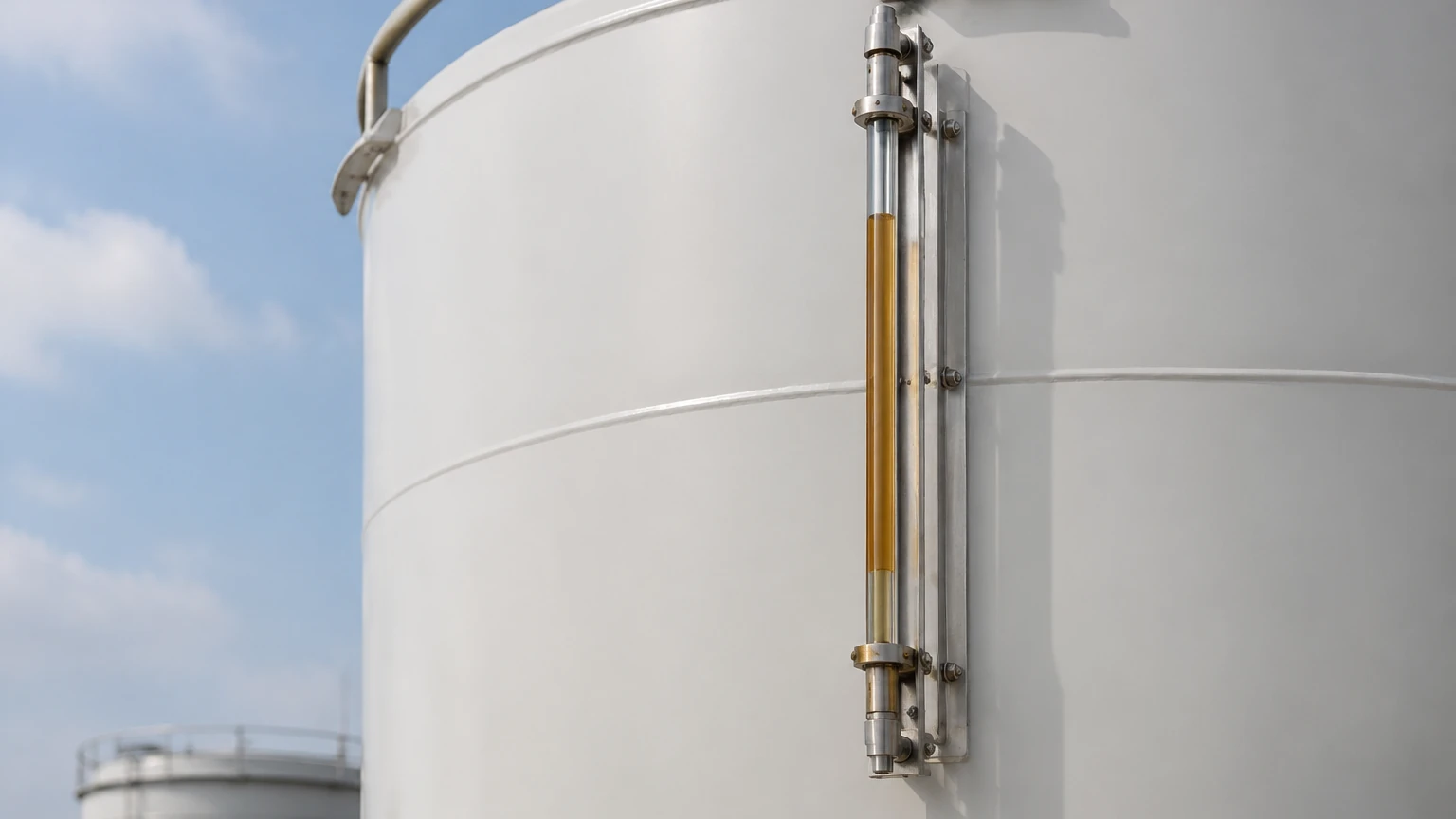
Magnetic level gauges and float switches rely on the buoyancy of a float designed to match the specific gravity of the oil. In a magnetic gauge, the float contains a permanent magnet that acts upon a series of external flaps or a transmitter outside the chamber. This provides a clear visual indication and can also generate a 4-20mA signal for remote monitoring.
Key Technologies for Oil Level Monitoring
Several distinct technologies serve as the primary device to check oil level in tank applications. Each has strengths depending on the tank geometry and the chemical properties of the oil.
1. Radar Level Meters
Radar technology is often considered the gold standard for oil storage. High-frequency radar (such as 80GHz or 26GHz) is unaffected by temperature fluctuations, pressure changes, or the presence of heavy vapors. Since oil has a low dielectric constant ($εr$), usually between 1.9 and 4.0, the radar signal must be sensitive enough to detect the weak reflection from the oil surface.
2. Ultrasonic Level Sensors
Ultrasonic sensors are cost-effective solutions for atmospheric tanks containing stable oils like diesel or lubricants. However, they are sensitive to air temperature changes and surface foam. If the oil is prone to outgassing or if the tank is pressurized, ultrasonic waves may be attenuated or distorted, leading to inaccurate readings.
3. Hydrostatic Level Transmitters
For underground storage tanks or deep reservoirs, hydrostatic transmitters are highly effective. These can be submersible (dropped into the tank) or flange-mounted at the bottom. They are rugged and simple to install, though they require the oil density to remain relatively constant to ensure the converted height measurement is precise.
4. Magnetic Level Gauges
In high-pressure or high-temperature oil applications, such as boiler fuel tanks or chemical reactors, magnetic level gauges offer a robust mechanical solution. They provide a high-visibility local display that does not require power, which is vital for safety during power outages. For digital integration, they can be equipped with reed chain transmitters.
Selection Criteria for Oil Tank Level Devices
Choosing the right instrument requires a comparison of technical specifications against the application's constraints. Use the following table as a preliminary selection guide for a device to check oil level in tank systems.
| Technology | Accuracy | Max Range | Typical Oil Types | Key Advantage |
| :— | :— | :— | :— | :— |
| Radar (Non-contact) | ±2 mm | Up to 120 m | Crude oil, heavy fuel, bitumen | High precision; works in vacuum/pressure. |
| Ultrasonic | ±0.5% FS | Up to 20 m | Diesel, hydraulic oil, lubricants | Non-contact; low maintenance; cost-effective. |
| Hydrostatic | ±0.25% FS | Up to 100 m | Refined oils, vegetable oils | Simple installation; ideal for deep tanks. |
| Magnetic Gauge | ±5 mm (Visual) | Up to 6 m | Fuel oil, thermal oil | No power required for local display; robust. |
| Level Switches | N/A (Point) | N/A | All types | Overfill protection and low-level alarms. |
When evaluating these options, users should consult the Main Page of professional manufacturers to review specific model capabilities and material compatibility charts.
Installation Best Practices and Considerations
The reliability of any device to check oil level in tank setups depends heavily on proper installation. Even the most advanced radar or ultrasonic sensor will fail if placed incorrectly.
1. Nozzle Placement: For non-contact sensors, the device should be mounted away from the tank wall to prevent false reflections (echoes). Typically, the sensor should be placed at 1/4 to 1/6 of the tank diameter from the wall.
2. Obstruction Clearance: Ensure the sensor's signal path is clear of internal obstructions such as heating coils, ladders, or agitators. If obstructions are unavoidable, many modern radar units offer "false echo suppression" software to ignore these signals.
3. Venting and Pressure: For hydrostatic sensors, the atmospheric reference tube in the cable must remain clear and dry. For ultrasonic sensors, ensure the tank is properly vented to prevent the buildup of vapors that could change the speed of sound.
4. Stillwells: In tanks with high turbulence or heavy foam, installing the sensor inside a stillwell (a vertical pipe) can provide a calm surface for more accurate measurement. This is common in crude oil storage.
Limitations and Troubleshooting Common Issues
No single device is perfect for every oil application. Understanding the limitations helps in proactive maintenance and troubleshooting.
* Dielectric Constant Limitations: Radar sensors require a minimum dielectric constant to "see" the liquid. If measuring very light hydrocarbons with a dielectric constant below 1.5, a guided wave radar (GWR) or a high-sensitivity pulsed radar may be necessary.
* Paraffin and Wax Buildup: In crude oil applications, paraffin wax can build up on contact probes or the lenses of non-contact sensors. Selecting a sensor with a flush-mounted antenna or a non-stick coating (like PTFE) can mitigate this risk.
* Density Fluctuations: If a hydrostatic transmitter is used in a tank where the oil temperature varies significantly (e.g., outdoor fuel tanks), the density will change. Without temperature compensation, the reported level will drift even if the actual volume remains the same.
* Foam Interference: Ultrasonic waves are often absorbed by surface foam. If the oil is being pumped into the tank at high velocity, creating foam, an ultrasonic sensor may lose its signal. Radar is generally better at penetrating foam, though heavy, dense foam can still affect performance.
Frequently Asked Questions (FAQs)
Q: Can I use the same device for both oil and water?
A: While many sensors can measure both, the settings must be adjusted. For example, the dielectric constant of water (≈80) is much higher than oil (≈2). A radar sensor calibrated for water may need its sensitivity increased to detect oil accurately. For hydrostatic sensors, the density setting must be changed from 1000 kg/m³ to the specific gravity of the oil (often 800-900 kg/m³).
Q: How do I measure oil level in a pressurized tank?
A: Radar and magnetic level gauges are the preferred choices for pressurized vessels. Ultrasonic sensors are generally not recommended for high-pressure environments because the change in gas density affects the speed of sound significantly.
Q: What is the best way to prevent tank overfills?
A: For safety-critical applications, it is best practice to use a continuous level transmitter (like radar) for inventory and a separate, independent level switch (like a tuning fork or float switch) for high-high level alarms and emergency shutdown (ESD).
Q: Are these devices compatible with explosive environments?
A: Most industrial oil tanks are classified as hazardous areas. Ensure the device to check oil level in tank has the appropriate certifications, such as ATEX, IECEx, or UL/CSA (Explosion-proof or Intrinsically Safe), before installation.
Conclusion
Selecting a device to check oil level in tank systems requires a balance of accuracy requirements, environmental conditions, and budget. Radar remains the most versatile choice for complex industrial processes, while hydrostatic and ultrasonic sensors offer reliable performance for simpler storage tasks. By understanding the underlying measurement principles and following rigorous installation standards, operators can ensure long-term reliability and safety in their oil management systems. For detailed product specifications and application support, engineers are encouraged to visit the Main Page to explore the full range of industrial level measurement solutions.