Level Fuel Sensor
Level Fuel Sensor
In industrial automation and process control, the accurate monitoring of fuel levels is a fundamental requirement for operational efficiency, safety, and inventory management. A level fuel sensor is a specialized instrument designed to measure the height, volume, or mass of liquid fuels—such as diesel, gasoline, kerosene, or heavy fuel oil—within storage tanks, day tanks, or process vessels. Given the volatile and often hazardous nature of these substances, selecting the appropriate measurement technology requires a deep understanding of physical principles and environmental constraints.
Industrial fuel measurement is not a one-size-fits-all application. The choice of sensor depends on the fuel’s chemical properties, the tank's physical dimensions, and the specific requirements of the control system. This guide examines the primary measurement principles, selection criteria, and installation best practices for industrial fuel level monitoring.
Measurement Principles for Fuel Level Sensing
Before selecting a sensor, it is essential to understand the underlying physics that govern how different instruments detect the fuel surface. Most industrial fuel sensors fall into one of four primary categories: Radar, Ultrasonic, Hydrostatic, and Magnetic.
1. Radar Level Measurement (Non-Contact and Guided)
Radar technology is widely considered the gold standard for fuel measurement due to its high accuracy and immunity to varying process conditions. It operates on the Time-of-Flight (ToF) principle.
* Non-Contact Radar: The sensor emits high-frequency electromagnetic pulses (typically 26 GHz or 80 GHz). These pulses travel to the fuel surface, reflect back, and are received by the antenna. The distance is calculated based on the time interval. Because radar waves do not require a medium for propagation, they are unaffected by vacuum, pressure, or temperature fluctuations in the vapor space.
* Guided Wave Radar (GWR): This technology uses a probe (cable or rod) to guide the electromagnetic pulse to the liquid surface. GWR is particularly effective in tanks with narrow geometries or internal obstructions, as the energy is concentrated along the probe, reducing signal loss and interference.
2. Ultrasonic Level Measurement
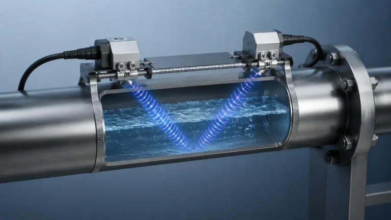
Ultrasonic sensors function similarly to radar but use sound waves instead of electromagnetic pulses. The sensor transmits an ultrasonic pulse that reflects off the fuel surface. The time taken for the echo to return determines the distance.
While cost-effective, ultrasonic sensors have limitations in fuel applications. Sound speed is affected by the composition of the air or gas in the tank's headspace. Since fuels often produce vapors that change the density of the air, ultrasonic sensors may require temperature compensation and may struggle with high-volatility fuels where vapor concentrations are inconsistent.
3. Hydrostatic Pressure Measurement
Hydrostatic sensors measure the pressure exerted by the liquid column above the sensor. The principle is based on the formula: $P = \rho \cdot g \cdot h$, where $P$ is pressure, $\rho$ is the density of the fuel, $g$ is gravity, and $h$ is the height of the liquid.
These sensors are typically submerged at the bottom of the tank or mounted to a flange at the base. They are highly reliable for vented tanks. However, because the measurement is density-dependent, any change in fuel temperature (which alters density) will affect the accuracy unless the system includes active density compensation.
4. Magnetic and Float-Based Measurement
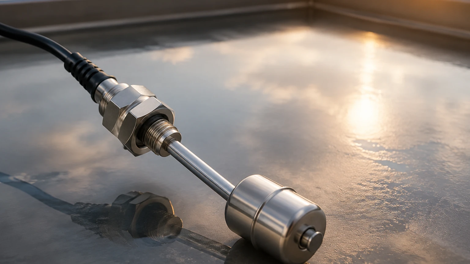
Magnetic level gauges and float switches use a buoyant float containing a magnet. As the fuel level rises or falls, the float moves along a tube. In a magnetic level gauge, the float’s magnet flips external flags or interacts with a reed switch array (magnetostrictive) to provide a continuous level reading. This is a mechanical-electronic hybrid approach that provides a clear visual indication alongside an electronic signal.
Key Evaluation Criteria for Selection
When evaluating a level fuel sensor for a specific project, engineers must confirm several technical parameters to ensure long-term reliability. For comprehensive technical specifications and product options, engineers can refer to the Main Page of professional instrumentation providers.
Fluid Properties and Dielectric Constant
For radar and capacitance-based sensors, the dielectric constant (εr) of the fuel is critical. Most hydrocarbon fuels have low dielectric constants (typically 1.9 to 2.1). This means they reflect radar signals weakly. Modern 80 GHz radar sensors are designed with high sensitivity to handle these low-reflectivity surfaces effectively.
Tank Environment and Geometry
* Internal Obstructions: Agitators, heating coils, and ladders can create false echoes. Guided wave radar or narrow-beam 80 GHz radar are preferred in these scenarios.
* Vapor and Foam: If the fuel tends to foam or produce heavy vapors, non-contact radar is generally superior to ultrasonic sensors.
* Pressure and Temperature: Ensure the sensor’s wetted materials and seals (e.g., Viton, Kalrez, or PTFE) are compatible with the fuel chemistry and the operating temperature range (typically -40°C to +80°C for standard fuel storage).
Accuracy and Output Requirements
Industrial applications usually require a 4-20mA HART, RS485 Modbus, or Foundation Fieldbus output for integration into a PLC or SCADA system. Accuracy requirements typically range from ±1 mm for high-precision custody transfer to ±10 mm for general inventory monitoring.
Practical Selection Table
| Technology | Accuracy | Suitability for Low Dielectric Fuels | Resistance to Vapor/Foam | Maintenance Level | Best Use Case |
| :— | :— | :— | :— | :— | :— |
| 80 GHz Radar | Excellent (±1mm) | High | Excellent | Very Low | High-precision storage, volatile fuels |
| Guided Wave Radar | High (±2mm) | High | Good | Low | Narrow tanks, internal obstructions |
| Ultrasonic | Moderate (±0.25% FS) | N/A | Low | Low | Diesel day tanks, non-volatile liquids |
| Hydrostatic | Good (±0.1% FS) | N/A | Excellent | Moderate | Underground tanks, vented vessels |
| Magnetic Float | Moderate (±5mm) | N/A | Excellent | Moderate | Visual bypass indication, high pressure |
Installation Considerations and Best Practices
Proper installation is as critical as sensor selection. Failure to follow engineering guidelines can lead to signal loss or inaccurate readings.
1. Avoid the "Dead Zone": Every sensor has a blocking distance or "dead zone" near the transmitter face where measurements are impossible. Ensure the sensor is mounted high enough that the maximum fuel level does not enter this zone.
2. Nozzle Dimensions: For non-contact radar, the mounting nozzle should be as short and wide as possible to prevent the signal from reflecting off the nozzle walls. If a long nozzle is required, the beam angle must be narrow enough to clear the nozzle exit.
3. Positioning: Sensors should not be installed directly above the fuel inlet to avoid turbulence and false readings during filling cycles. They should also be mounted away from the tank wall (typically at 1/4 to 1/6 of the tank diameter) to avoid side-wall interference.
4. Grounding and Shielding: To prevent electromagnetic interference (EMI) from pumps or motors, use shielded cables and ensure the instrument is properly grounded according to the manufacturer’s specifications.
5. Safety Certifications: Since fuel environments are often classified as hazardous areas, sensors must carry appropriate certifications such as ATEX, IECEx, or UL/CSA for Zone 0 or Zone 1 environments.
Limitations and Common Risks
Despite advancements in technology, certain risks remain inherent in fuel level sensing:
* Build-up and Coating: Heavy fuel oils (HFO) can leave deposits on probes or lenses. While radar can often "see through" thin coatings, significant build-up on an ultrasonic transducer or a GWR probe will eventually cause signal degradation.
* Specific Gravity Fluctuations: Hydrostatic sensors rely on a constant density. If a facility switches from one fuel grade to another with a different specific gravity without recalibrating the transmitter, the level reading will be incorrect.
* Surface Turbulence: Rapid filling or agitators can create waves. Software-based damping and signal averaging can mitigate this, but physical stilling wells are sometimes necessary for extreme turbulence.
Frequently Asked Questions (FAQs)
Q: Can I use an ultrasonic sensor for gasoline?
A: It is generally not recommended. Gasoline is highly volatile, and the resulting vapors change the speed of sound in the tank headspace, leading to significant errors. Radar is a much more reliable choice for gasoline.
Q: How does the dielectric constant affect radar measurement?
A: The dielectric constant determines how much energy is reflected back to the sensor. Low dielectric fluids like fuel reflect less energy. If the dielectric is too low (below 1.4), a guided wave radar or a high-frequency non-contact radar is required to capture a usable signal.
Q: Is hydrostatic measurement suitable for pressurized fuel tanks?
A: Standard hydrostatic sensors measure relative pressure (gauge pressure). In a pressurized tank, you would need a differential pressure (DP) transmitter to subtract the headspace pressure from the total pressure at the bottom.
Q: What maintenance is required for a non-contact radar sensor?
A: Non-contact radar is virtually maintenance-free because it has no moving parts and does not touch the fuel. Periodic inspection of the antenna for heavy condensation or debris is usually sufficient.
Conclusion
Selecting the right level fuel sensor involves balancing technical requirements with budget constraints and environmental realities. For most modern industrial applications, radar technology offers the most robust performance, particularly in the face of low dielectric fuels and volatile vapors. However, hydrostatic and magnetic solutions remains viable for specific configurations such as vented underground tanks or applications requiring mechanical redundancy.
Before finalizing a system design, engineers should confirm the chemical compatibility of wetted parts, the required safety ratings for hazardous zones, and the integration capabilities of the sensor with existing control architectures. For more detailed application engineering and a full range of measurement solutions, visit the Main Page to explore professional-grade instrumentation options tailored to industrial fuel management.