Fluid Sensors
Fluid Sensors
In industrial process control, fluid sensors serve as the primary interface between physical liquid states and automated management systems. These instruments are critical for ensuring safety, efficiency, and inventory accuracy across sectors such as water treatment, chemical processing, and oil and gas production. Selecting the appropriate sensor requires a technical understanding of how different technologies interact with various fluid properties and vessel geometries.
Core Measurement Principles
Before selecting a device, it is essential to understand the physics governing the most common industrial fluid sensors. These technologies are generally categorized into non-contact and contact measurement methods.
Radar Level Measurement (ToF and FMCW)
Radar fluid sensors utilize electromagnetic waves to determine the distance to a liquid surface. There are two primary types: Pulse Radar (Time of Flight) and Frequency Modulated Continuous Wave (FMCW).
Pulse radar emits a high-frequency signal that reflects off the fluid surface and returns to the sensor. The distance is calculated based on the time it takes for the pulse to travel. FMCW radar, often operating at 26GHz or 80GHz, emits a continuous signal with a changing frequency. The difference between the emitted and received frequency is proportional to the distance. Radar is highly valued because electromagnetic waves are largely unaffected by temperature, pressure, or vacuum conditions. However, the dielectric constant (εr) of the fluid is a critical factor; liquids with low dielectric constants (like certain hydrocarbons) reflect less energy, requiring more sensitive antenna configurations.
Ultrasonic Level Measurement
Ultrasonic sensors function by emitting high-frequency sound waves (typically 20 kHz to 200 kHz). These waves travel through the air, bounce off the liquid surface, and return to the transducer. Unlike radar, the speed of sound is heavily dependent on the temperature and density of the air or gas through which it travels. Most modern ultrasonic fluid sensors include integrated temperature compensation to maintain accuracy. These are cost-effective solutions for water and wastewater applications but are generally unsuitable for vacuum environments or processes with heavy foam, which can absorb the acoustic signal.
Hydrostatic Pressure Measurement
Hydrostatic sensors operate on the principle that the pressure at the bottom of a vessel is directly proportional to the height of the liquid column above it, according to the formula: $P = \rho \cdot g \cdot h$ (where $P$ is pressure, $\rho$ is fluid density, $g$ is gravity, and $h$ is height). These sensors can be submersible (lowered into the fluid) or externally mounted via a flange or thread at the bottom of the tank. The primary limitation is that any change in fluid density—caused by temperature fluctuations or chemical composition changes—will result in a measurement error unless the system is recalibrated or compensated.
Magnetic Level Gauges
Magnetic fluid sensors utilize a float containing an internal magnet assembly that moves with the liquid level. This float is housed within a non-magnetic chamber. Outside the chamber, a visual indicator (flags or rollers) or a continuous transmitter (reed chain or magnetostrictive) tracks the float's position through magnetic coupling. This method provides a clear physical visual and a reliable electronic signal without the fluid ever coming into contact with the electronic components.
Key Evaluation Criteria for Sensor Selection
Choosing the right instrument involves more than matching a sensor to a tank. Engineers must evaluate the chemical and physical environment to ensure long-term reliability. For a detailed look at specific instrument specifications, technical teams often refer to the Main Page of professional equipment manufacturers to compare model-specific tolerances.
1. Fluid Characteristics:
* Viscosity: Highly viscous fluids can cause build-up on contact sensors like tuning forks or hydrostatic diaphragms.
* Corrosivity: Acids and bases require specific housing materials such as PTFE (Polytetrafluoroethylene), PVDF, or high-grade stainless steel (316L).
* Dielectric Constant: For radar sensors, a dielectric constant below 1.9 typically requires a guided wave radar (GWR) or a high-sensitivity 80GHz beam.
2. Process Conditions:
* Temperature: Standard sensors may handle up to 80°C (176°F), but specialized high-temperature versions are required for steam or molten processes, often reaching 250°C (482°F) or higher.
* Pressure: Vacuum conditions eliminate the use of ultrasonic sensors, while high-pressure vessels (above 40 bar / 580 psi) require robust radar or magnetic gauge housings.
3. Vessel Geometry:
* The presence of agitators, heating coils, or internal ladders can create false echoes for non-contact sensors. In these cases, narrow-beam radar or guided wave radar is preferred.
Practical Selection Matrix
The following table provides a general guideline for matching fluid sensors to common industrial scenarios.
| Technology | Best Application | Limitations | Typical Accuracy |
| :— | :— | :— | :— |
| 80GHz Radar | Small tanks, narrow nozzles, corrosive liquids | Very low dielectric fluids (without GWR) | ±1 mm |
| Ultrasonic | Open channels, water sumps, plastic tanks | Foam, vacuum, high dust, high temp | ±0.25% of range |
| Hydrostatic | Deep wells, vented fuel tanks, constant density liquids | Changing fluid density, pressurized tanks | ±0.1% to 0.5% span |
| Magnetic Gauge| High-pressure boilers, oil/water interface | High viscosity (float sticking), solids | ±5 mm (visual) |
| Level Switches| Overfill protection, pump dry-run prevention | Point level only (no continuous data) | N/A |
Installation Considerations and Best Practices
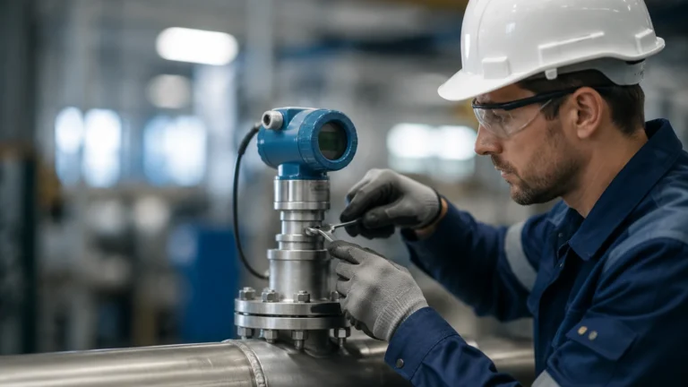
Correct installation is as vital as sensor selection. Even the most advanced fluid sensors will provide inaccurate data if mounted incorrectly.
* Dead Zones (Blocking Distance): All non-contact sensors have a minimum distance near the transducer where they cannot measure. For ultrasonic sensors, this might be 0.2m to 0.5m (8" to 20"). Ensure the sensor is mounted high enough that the maximum liquid level never enters this zone.
* Nozzle Geometry: If mounting on a nozzle, the diameter and height of the nozzle must not interfere with the signal beam. For radar, the beam should ideally be clear of the nozzle edge to prevent "ringing" or false reflections.
* Avoiding Obstructions: Sensors should be positioned away from the center of the tank (to avoid concave reflections) and away from the tank wall (to avoid side-lobe interference). A common rule of thumb is to mount the sensor at 1/6th of the tank diameter from the wall.
* Stilling Wells: In turbulent tanks with heavy agitation or surface rippling, installing the sensor (radar or ultrasonic) inside a stilling well or bypass pipe can provide a stable surface for measurement.
Operational Limitations and Environmental Risks
Engineers must account for the following risks that can compromise fluid sensors:
* Vapor and Condensation: In closed tanks, condensation can form on the sensor face. While some radar sensors are designed with convex lenses to shed droplets, heavy condensation can still attenuate ultrasonic signals.
* Foam: Surface foam is the primary enemy of non-contact sensors. Light, airy foam can absorb ultrasonic pulses, while thick, dense foam can reflect radar signals prematurely, leading to a "tank full" error when the tank is actually empty.
* Build-up and Scaling: In wastewater or mining slurries, material can build up on the sensor. Hydrostatic diaphragms are particularly sensitive to this, as the weight of the build-up adds to the perceived pressure.
* Electromagnetic Interference (EMI): In heavy industrial environments, poorly shielded cables can pick up noise from VFDs (Variable Frequency Drives) or large motors, distorting the 4-20mA or RS485 signal from the sensor.
Frequently Asked Questions (FAQ)
Q: Can I use one sensor for multiple types of fluids?
A: It depends on the technology. Radar is generally versatile across different fluids as long as the dielectric constant is sufficient. Hydrostatic sensors, however, must be recalibrated if the fluid density changes (e.g., switching from water to oil).
Q: What is the difference between a level transmitter and a level switch?
A: A transmitter provides continuous measurement (e.g., 0% to 100% full), typically outputting a 4-20mA or digital signal. A level switch is a point-level device that only triggers when the fluid reaches a specific height, used primarily for alarms or pump control.
Q: How often do fluid sensors need calibration?
A: Most digital radar and ultrasonic sensors are factory-calibrated and do not drift over time. However, hydrostatic sensors and magnetic transmitters should be checked annually to account for diaphragm fatigue or magnetic degradation.
Q: Is 80GHz radar always better than 26GHz?
A: Not necessarily. While 80GHz offers a narrower beam and better resolution for small tanks, 26GHz may be more effective in environments with heavy steam or dust, as the longer wavelength can penetrate these atmospheric obstacles more effectively.
For technical professionals seeking to integrate these systems into a larger automation framework, reviewing the Main Page of a dedicated manufacturer provides the necessary data sheets and certification documents (such as ATEX or SIL2) required for industrial compliance. Selecting the right fluid sensors is a balance of physics, chemistry, and mechanical engineering, ensuring that the heart of the process remains visible and controlled.