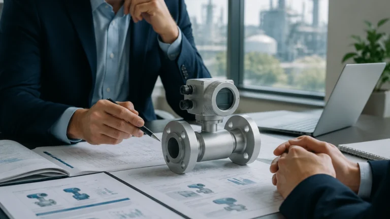
Remote Water Tank Level Indicator
Remote Water Tank Level Indicator
In industrial water management, the ability to monitor liquid volumes from a distance is a fundamental requirement for operational efficiency and safety. A remote water tank level indicator is not a single device but a system comprising a primary sensing element, a signal transmitter, and a remote display or control interface. These systems eliminate the need for manual inspections, which are often hazardous or impractical in large-scale facilities such as chemical plants, water treatment works, and remote oil and gas installations.
Selecting the appropriate technology for a remote water tank level indicator requires a deep understanding of the physical principles governing level measurement. This guide explores the primary technologies used in modern industrial applications, their selection criteria, and the engineering considerations necessary for successful deployment.
Measurement Principles of Remote Level Indicators
To achieve reliable remote monitoring, the sensor must convert the physical level of the water into an electrical signal that can travel over distances without significant degradation. The following four technologies represent the industry standard for industrial water tank applications.
1. Ultrasonic Level Measurement
Ultrasonic sensors operate on the "Time-of-Flight" (ToF) principle. The sensor, mounted at the top of the tank, emits a high-frequency sound pulse. This pulse travels through the air, reflects off the water surface, and returns to the transducer. By measuring the time taken for the echo to return, the system calculates the distance to the liquid surface.
* Advantages: Non-contact measurement, no moving parts, and relatively low maintenance.
* Limitations: Performance can be affected by heavy foam, extreme steam, or high-pressure fluctuations that alter the speed of sound in the tank headspace.
2. Radar (GWR and Non-Contact) Level Measurement
Radar technology also uses the ToF principle but employs electromagnetic waves (microwaves) instead of sound. Non-contact radar emits waves through the air, while Guided Wave Radar (GWR) sends the signal down a probe or cable submerged in the liquid.
* Advantages: Highly accurate (often to within ±1 mm), unaffected by temperature, pressure, or dust. Radar can penetrate steam and is more resilient to foam than ultrasonic sensors.
* Limitations: Higher initial capital expenditure compared to other methods.
3. Hydrostatic Pressure Measurement
Hydrostatic transmitters measure the pressure exerted by the liquid column at the bottom of the tank. The principle is based on the formula $P = \rho gh$, where $P$ is pressure, $\rho$ is the liquid density, $g$ is gravity, and $h$ is the height of the liquid. A submersible pressure transducer or a flange-mounted transmitter converts this pressure into a level reading.
* Advantages: Ideal for very deep tanks or underground reservoirs; simple installation for vented tanks.
* Limitations: Accuracy depends on constant liquid density. If the water temperature or chemical composition changes significantly, the density shift may cause errors.
4. Magnetic Level Gauges with Transmitters
Magnetic level gauges utilize a float containing a permanent magnet that moves with the liquid level inside a bypass chamber. For remote indication, a reed switch array or a magnetostrictive transmitter is mounted to the outside of the chamber. As the float moves, it triggers the transmitter to send a continuous 4-20mA or digital signal.
* Advantages: Provides both a local visual high-visibility display and a remote electronic signal; excellent for high-pressure or high-temperature water tanks.
* Limitations: Requires a bypass chamber (side-mounting), which may not be feasible for all tank geometries.
System Architecture for Remote Monitoring
A remote water tank level indicator system is defined by how it communicates data from the tank to the end-user. Modern industrial systems generally fall into three architectural categories:
Wired Analog and Digital Loops
The most traditional method involves a 4-20mA current loop. The sensor acts as a current source, and the remote indicator (usually a panel meter or PLC input) measures the current. Digital protocols like HART (Highway Addressable Remote Transducer) can be superimposed on the 4-20mA signal to provide diagnostic data. RS485 Modbus is also common for multi-drop configurations where several tanks are monitored on a single cable run.
Wireless IoT Integration
For remote sites where cabling is cost-prohibitive, wireless technologies such as LoRaWAN, NB-IoT, or cellular (4G/5G) are utilized. These systems use battery-powered or solar-powered transmitters to send level data to a gateway or cloud platform. This allows operators to view tank levels on mobile devices or centralized SCADA systems from anywhere in the world.
Local-to-Remote Display Units
In many B2B applications, a dedicated remote indicator is mounted at eye level at the base of a tall tank or in a nearby control room. These units often provide power to the sensor (loop power) and feature programmable alarms, relays for pump control, and bright LED/LCD readouts.
Selection Criteria for Industrial Applications
Choosing the right remote water tank level indicator involves balancing technical requirements with budget constraints. The following table provides a comparison for common industrial scenarios.
| Technology | Typical Range | Accuracy | Best Environment | Relative Cost |
| :— | :— | :— | :— | :— |
| Ultrasonic | 0.25m – 15m | ±0.25% | Open basins, vented tanks | Moderate |
| Radar (80GHz) | 0.1m – 30m+ | ±1mm | Process tanks, steam, foam | High |
| Hydrostatic | 1m – 200m | ±0.1% to 0.5% | Deep wells, reservoirs | Low to Moderate |
| Magnetic | 0.3m – 6m | ±5mm | High-pressure boilers, chemical storage | Moderate to High |
Engineering and Installation Considerations
To ensure the longevity and accuracy of a remote water tank level indicator, engineers must adhere to specific installation guidelines:
1. Dead Zone Management: Every non-contact sensor (ultrasonic and radar) has a "dead zone" or "blocking distance" near the sensor face where measurement is impossible. The sensor must be mounted high enough above the maximum fill level to prevent the water from entering this zone.
2. Mounting Position: Sensors should be installed away from the tank's inlet flow to avoid turbulence and false readings. For ultrasonic sensors, they must be mounted perpendicular to the liquid surface and away from internal tank structures like ladders or agitators that could cause false echoes.
3. Cable Shielding: In wired systems, signal cables should be shielded and separated from high-voltage power lines to prevent electromagnetic interference (EMI) from distorting the level signal.
4. Venting: For hydrostatic transmitters, the reference side of the sensor must be vented to the atmosphere to compensate for changes in barometric pressure, unless the tank is sealed and a differential pressure setup is used.
5. Environmental Protection: For outdoor water tanks, indicators and transmitters should have an IP67 or IP68 rating to protect against moisture ingress and UV radiation.

Common Risks and Mitigation
Deploying a remote water tank level indicator is not without risks. Engineers should be aware of the following potential failure points:
* Signal Loss in Wireless Systems: In remote areas, signal attenuation due to terrain or weather can lead to data gaps. Using high-gain antennas or mesh networking can mitigate this.
* Scaling and Buildup: In hard water applications, mineral buildup on ultrasonic transducers or hydrostatic diaphragms can cause drift. Regular maintenance schedules and the use of PTFE-coated sensors can reduce this risk.
* Lightning Strikes: Outdoor tanks are susceptible to lightning. Installing surge protection devices (SPDs) on both the sensor end and the indicator end of the loop is critical for protecting the electronics.
Frequently Asked Questions (FAQ)
Q: Can a remote water tank level indicator also control a pump?
A: Yes. Most remote indicators feature relay outputs that can be programmed to start a pump at a "Low" setpoint and stop it at a "High" setpoint, providing automated level control.
Q: How far can the remote display be from the water tank?
A: For wired 4-20mA systems, distances of up to 1,000 meters are possible with high-quality shielded cabling. For wireless LoRaWAN systems, distances can exceed 5-10 kilometers depending on the line of sight.
Q: Is calibration required for these sensors?
A: Most modern digital sensors come factory-calibrated. However, site-specific calibration (mapping the 4mA and 20mA points to empty and full states) is necessary during commissioning to account for tank geometry.
Conclusion
Implementing a robust remote water tank level indicator system requires a systematic approach to sensor selection and installation. By understanding the underlying physics—whether it be the acoustics of ultrasonics or the pressure dynamics of hydrostatics—engineers can ensure reliable data delivery for critical process decisions. For a comprehensive overview of available technologies and specific product specifications, professionals should Review product options and application support on our Main Page to find the solution that best fits their industrial requirements.
Before finalizing a project, it is recommended that stakeholders confirm the chemical compatibility of the sensor materials with the stored water (especially if treated with chlorine or other chemicals) and verify the power availability at the tank site to determine if a wired or wireless architecture is most feasible.