Fluid Line
Fluid Line
In industrial process control, the precise identification and monitoring of the fluid line—the interface between a liquid and the gas or vapor space above it—is fundamental to operational safety, inventory management, and process efficiency. Whether managing a volatile chemical reagent, a municipal water reservoir, or crude oil in a separator, engineers must rely on robust instrumentation to track this boundary under varying pressures, temperatures, and physical conditions.
Welk, as a professional manufacturer of industrial level measurement instruments, provides a diverse range of technologies designed to detect the fluid line with high accuracy. Understanding the underlying physics of these measurement principles is the first step in selecting the appropriate sensor for a specific application. This guide explores the technical methodologies, selection criteria, and installation best practices for maintaining precise fluid line visibility in modern industrial environments.
Principles of Detecting the Fluid Line
To accurately track a fluid line, instrumentation must interact with the physical properties of the media, such as its dielectric constant, density, or acoustic reflectivity. The most common industrial methods include radar, ultrasonic, hydrostatic, and magnetic technologies.
Radar Level Measurement (Non-Contact and Guided)
Radar technology utilizes electromagnetic pulses to detect the fluid line. In non-contact radar, the sensor emits a high-frequency signal (typically in the 26GHz or 80GHz range) toward the liquid surface. When the signal hits the fluid line, a portion of the energy is reflected back to the receiver. The instrument calculates the distance based on the time-of-flight of the signal.
* FMCW (Frequency Modulated Continuous Wave): Modern radar meters often use FMCW, where the transmitted frequency increases linearly. The difference between the transmitted and received frequency is proportional to the distance to the fluid line. This method offers superior accuracy and signal-to-noise ratios.
* Dielectric Dependency: The strength of the reflection is determined by the dielectric constant ($ε_r$) of the fluid. Fluids with high $ε_r$, such as water, provide very strong reflections, while hydrocarbons with low $ε_r$ may require more sensitive electronics or guided wave radar (GWR) where the signal travels along a probe.
Ultrasonic Level Measurement
Ultrasonic sensors track the fluid line by emitting ultrasonic sound waves (mechanical energy). The waves travel through the air, bounce off the liquid surface, and return to the transducer.
* Speed of Sound: This method depends on the speed of sound in the vapor space. Since temperature significantly affects the speed of sound, high-quality ultrasonic sensors include integrated temperature compensation to ensure the calculated fluid line remains accurate despite ambient fluctuations.
* Application Scope: Ultrasonic measurement is ideal for open-channel flow and atmospheric tanks, particularly in water and wastewater treatment, where the media is non-volatile and the vapor space is relatively stable.
Hydrostatic Pressure Measurement
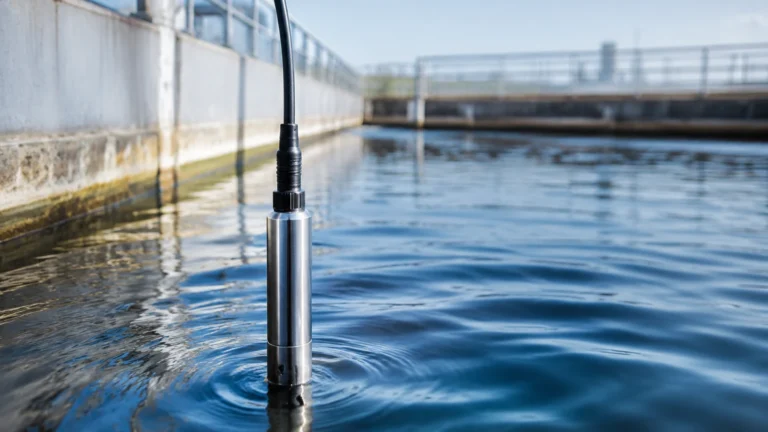
Hydrostatic transmitters detect the fluid line by measuring the pressure exerted by the liquid column. According to the principle of hydrostatics, the pressure ($P$) at the bottom of a tank is proportional to the height of the liquid ($h$), the density of the fluid ($ρ$), and gravity ($g$): $P = ρgh$.
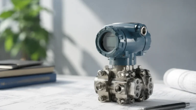
* Vented vs. Pressurized: In atmospheric tanks, a simple pressure transmitter at the base can determine the level. In pressurized vessels, a differential pressure (DP) transmitter is required to subtract the headspace pressure from the total bottom pressure, isolating the pressure generated solely by the fluid column.
Magnetic Level Gauges
Magnetic gauges provide both visual indication and electronic feedback of the fluid line. A bypass chamber is mounted to the side of the vessel, and a float containing an internal magnet assembly moves with the fluid level.
* Magnetic Coupling: As the float rises and falls, it magnetically couples with a series of bi-color flaps on an external scale or a magnetostrictive transmitter. This provides a highly reliable, power-free visual reference of the fluid line, which is critical for safety-instrumented systems (SIS).
Key Evaluation Criteria for Level Measurement
Selecting the right instrument to monitor a fluid line requires a comprehensive evaluation of the process environment. Engineers should consider the following factors:
1. Media Characteristics: Is the fluid corrosive, viscous, or prone to coating? For corrosive fluids, non-contact methods like radar or ultrasonic are preferred to minimize maintenance. For coating fluids, radar with high-frequency beams can often "see through" minor buildup on the antenna.
2. Process Conditions: High pressures and temperatures can disqualify certain technologies. Radar and magnetic gauges are generally more resilient to extreme conditions than ultrasonic sensors.
3. Accuracy Requirements: For custody transfer or high-value chemical dosing, high-frequency radar (80GHz) provides millimeter-level precision. For general sump monitoring, hydrostatic or ultrasonic sensors offer a more cost-effective solution.
4. Vapor Space Dynamics: The presence of heavy steam, foam, or dust can interfere with signal transmission. Radar is generally more effective at penetrating dust and steam than ultrasonic waves, though heavy foam can absorb signals from both.
For a detailed look at specific hardware configurations for these applications, users can consult the Welk Main Page to review product options and application support.
Practical Selection Table for Different Media
The following table provides a general guideline for selecting a technology based on the type of fluid and the environment surrounding the fluid line.
| Media Type | Recommended Technology | Primary Advantage | Limitations |
| :— | :— | :— | :— |
| Water/Wastewater | Ultrasonic | Low cost, easy installation | Affected by heavy foam and wind |
| Corrosive Chemicals | Non-contact Radar | No wetted parts (PTFE options) | Requires minimum dielectric constant |
| High-Temp Oil | Magnetic Level Gauge | High visibility, no power needed | Float must match fluid density |
| Slurries/Pastes | Hydrostatic (Flush Diaphragm) | Resists clogging | Sensitive to density changes |
| Pressurized Gases | Guided Wave Radar | Immune to vapor space changes | Probe is a wetted part |
| Clean Liquids | Hydrostatic Transmitter | Simple, reliable, and compact | Not suitable for varying densities |
Installation Considerations for Accurate Tracking
Even the most advanced sensor will fail to track the fluid line accurately if installed incorrectly. Proper engineering placement is vital.
Avoiding Obstructions
Internal tank structures such as agitators, heating coils, and ladders can create "false echoes" for radar and ultrasonic sensors. Modern instruments feature "false echo suppression" software, but it is best practice to mount the sensor at a distance from these obstructions. For radar, the beam angle should be calculated to ensure the signal path is clear of the tank wall and internal hardware.
Managing Turbulence and Foam
In tanks with heavy agitation, the fluid line may be turbulent, causing signal scattering. Installing the sensor inside a stilling well or a bypass chamber can stabilize the surface, providing a clean fluid line for the instrument to track. Stilling wells are particularly effective for low-dielectric fluids measured with radar.
Dead Zones (Blocking Distance)
Every non-contact sensor has a "dead zone" or "blocking distance" directly beneath the transducer where measurements cannot be taken. For example, an ultrasonic sensor might have a dead zone of 0.25m (approx. 10 inches). If the fluid line rises into this zone, the sensor will provide an error or an incorrect reading. Engineers must ensure the sensor is mounted high enough to accommodate the maximum fill level.
Nozzle Geometry
The mounting nozzle should be short and wide enough to prevent the signal from reflecting off the nozzle walls before it reaches the tank interior. For 80GHz radar, which has a very narrow beam, nozzle interference is less of a concern than with lower-frequency models.

Limitations and Common Risks
While modern instrumentation is highly capable, certain physical limitations must be acknowledged to avoid process failures.
* Density Fluctuations: Hydrostatic level measurement is entirely dependent on fluid density. If a process involves mixing different liquids or significant temperature swings that change the density, the reported fluid line will shift even if the actual volume remains constant.
* Vacuum Conditions: Ultrasonic waves require a medium (air or gas) to travel. In a vacuum, ultrasonic sensors cannot function, making radar or magnetic gauges the only viable options.
* Dielectric Limits: For non-contact radar, if the fluid has an extremely low dielectric constant (e.g., certain liquefied gases), the signal may pass right through the fluid line and reflect off the bottom of the tank. In these cases, guided wave radar or magnetic gauges are necessary.
* Foam Interference: Thick, dense foam can act as a false fluid line or absorb the signal entirely. Selecting the right frequency and potentially using a stilling well are common mitigation strategies.
Frequently Asked Questions (FAQs)
Q: How do I measure the fluid line if there is a layer of foam on top?
A: If the foam is light, high-frequency radar can often penetrate it to reach the liquid surface. If the foam is thick and dense, a hydrostatic transmitter or a magnetic level gauge is more reliable, as they respond to the mass or buoyancy of the liquid rather than the surface reflection.
Q: Can one sensor track the interface between two different liquids?
A: Yes. Guided Wave Radar (GWR) is particularly effective at measuring both the upper fluid line and the interface between two liquids (e.g., oil and water), provided the upper liquid has a lower dielectric constant than the lower liquid.
Q: What is the maximum range for tracking a fluid line?
A: This depends on the technology. High-end radar units can track fluid lines at distances exceeding 70 meters (approx. 230 feet), while ultrasonic sensors are typically limited to 15-30 meters (approx. 50-100 feet).
Q: Is maintenance required for non-contact sensors?
A: Generally, very little. Because they do not touch the media, there is no wear or corrosion. However, periodic checks to ensure the antenna is free of heavy condensation or crystallized buildup are recommended in certain chemical applications.
Conclusion
Maintaining an accurate reading of the fluid line is a cornerstone of industrial automation. By understanding the physical principles of radar, ultrasonic, hydrostatic, and magnetic measurement, engineers can select a solution that balances cost, accuracy, and reliability. Proper installation—accounting for dead zones, tank internals, and media properties—ensures that the instrumentation provides actionable data for years to come. For those seeking specific hardware specifications or customized OEM/ODM level measurement solutions, visiting the Main Page of the manufacturer’s site offers a direct path to technical support and product selection tools.