Ultrasonic Level Sensor Keyence
A Comprehensive Guide to Ultrasonic Level Measurement: Evaluating Ultrasonic Level Sensor Keyence and Industrial Solutions
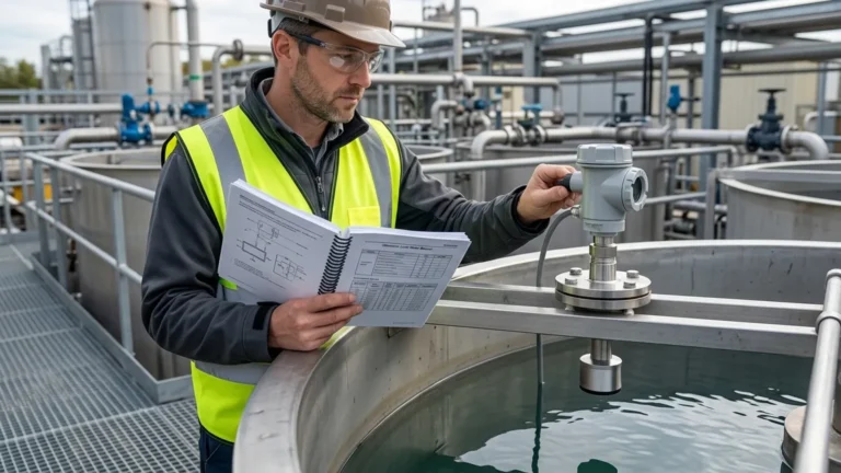
In the landscape of industrial automation, non-contact level measurement has become the standard for efficiency and reliability. Engineers and procurement specialists often evaluate high-precision options like the ultrasonic level sensor Keyence offers for factory automation, while also considering robust industrial-grade Ultrasonic Level Meters for large-scale process control.
Choosing the right technology requires a deep understanding of how ultrasonic waves interact with the environment and the specific requirements of the medium being measured. This guide explores the principles, selection criteria, and practical installation strategies for ultrasonic level measurement in B2B environments.
Understanding the Measurement Principle
Ultrasonic level measurement is based on the "Time-of-Flight" (ToF) principle. The sensor, acting as a transducer, emits high-frequency sound pulses (typically between 20 kHz and 200 kHz). These pulses travel through the air, reflect off the surface of the target medium, and return to the transducer.
The distance ($D$) between the sensor and the material surface is calculated using the formula:
$$D = \frac{c \times t}{2}$$
Where:
* c is the speed of sound in the medium (usually air).
* t is the total time elapsed from emission to reception.
Since the height of the vessel ($H$) is a known constant, the actual level ($L$) of the material is determined by subtracting the measured distance from the total height ($L = H – D$).
The Role of Temperature Compensation
The speed of sound in air is approximately 331.5 m/s at 0°C, but it changes by roughly 0.6 m/s for every degree Celsius change in temperature. For an ultrasonic level sensor Keyence or Welk industrial meter to maintain accuracy, integrated temperature sensors are essential to adjust the calculation in real-time. Without this compensation, a 10°C shift could result in a measurement error of nearly 2%.
Evaluating Ultrasonic Level Sensor Keyence vs. Industrial Meters
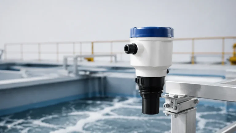
When searching for an ultrasonic level sensor Keyence, users are typically looking for compact, high-performance sensors designed for discrete manufacturing and small-tank applications. Keyence sensors, such as the FW series, are renowned for their ability to detect targets regardless of color or transparency, making them excellent for assembly lines.
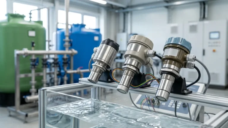
However, in heavy industrial sectors—such as water treatment, chemical processing, and oil and gas—the requirements often shift toward Ultrasonic Level Meters that provide higher environmental protection (IP68), longer ranges (up to 30 or 40 meters), and specialized communication protocols like HART or Modbus. Welk specializes in these robust industrial solutions, providing the durability needed for outdoor or corrosive environments.
Key Differences at a Glance
| Feature | Compact Automation Sensors (e.g., Keyence) | Industrial Level Meters (e.g., Welk) |
| :— | :— | :— |
| Primary Use | Detection on assembly lines, small tanks | Large storage tanks, open channels, sumps |
| Measurement Range | Typically 0.1m to 3m | Up to 15m (standard) or 40m (extended) |
| Output Options | Digital/NPN/PNP, 4-20mA | 4-20mA, HART, RS485/Modbus, Relays |
| Enclosure Rating | Often IP67 | IP67 or IP68 (Submersible) |
| Display | Integrated OLED/LED | Large LCD with trend graphing |
Key Evaluation Criteria for Selection
Selecting the correct instrument involves more than just matching a range. Engineers must consider the physical and chemical properties of the application.
1. The "Dead Zone" (Blocking Distance)
Every ultrasonic sensor has a minimum distance near the transducer face where it cannot accurately process a return signal. This is known as the dead zone. If the liquid level enters this zone, the meter will provide erratic readings. Standard industrial meters usually have a dead zone of 0.25m to 0.5m. When selecting an ultrasonic level sensor Keyence for a shallow tank, ensure the dead zone is small enough to accommodate the maximum fill level.
2. Beam Angle and Obstructions
The ultrasonic pulse spreads as it travels, forming a cone. The beam angle (typically 5° to 12°) determines the footprint of the signal at the maximum range. If the beam hits a tank wall, ladder, or agitator, it will create a false echo.
3. Material Compatibility
For corrosive liquids like acids or alkalis, the transducer face must be made of resistant materials. While standard sensors use ABS or PVC, industrial applications often require PVDF (Polyvinylidene Fluoride) or PTFE coatings to prevent chemical degradation.
Practical Selection Table
Use the following table to narrow down the technology based on common industrial scenarios:
| Application Scenario | Recommended Range | Required Feature | Suggested Technology |
| :— | :— | :— | :— |
| Small Chemical Tote | 0.2m – 2.0m | PVDF Transducer | Compact Ultrasonic Sensor |
| Wastewater Sump | 1.0m – 10.0m | IP68 Rating | Submersible Industrial Meter |
| Open Channel Flow | 0.5m – 5.0m | Flume/Weir Algorithms | Ultrasonic Flow/Level Meter |
| High-Speed Packaging | 0.05m – 1.0m | High Sampling Rate | ultrasonic level sensor keyence |
| Large Oil Storage | 2.0m – 20.0m | Explosion Proof (Ex d) | Long-Range Radar or Ultrasonic |
Installation Considerations and Best Practices
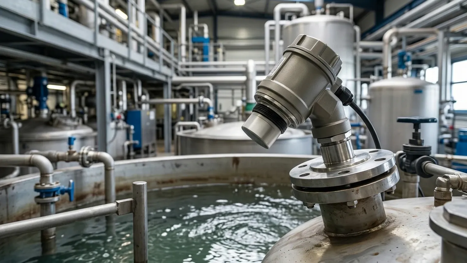
Correct installation is the most significant factor in the long-term success of an ultrasonic measurement system.
1. Perpendicular Alignment: The transducer face must be perfectly parallel to the liquid surface. A tilt of even a few degrees can cause the reflected signal to miss the receiver, leading to a "Loss of Echo" error.
2. Avoid the Fill Path: Never install a sensor directly above the inlet where the liquid enters the tank. The turbulence and falling material will scatter the ultrasonic signal.
3. Standpipe Usage: In tanks with heavy foam or narrow geometries, a standpipe (still-well) can be used to guide the ultrasonic wave. However, the pipe must be smooth and free of burrs on the inside.
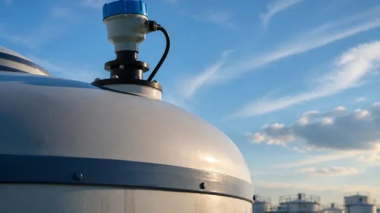
4. Sunlight Protection: For outdoor installations, a sunshade is recommended. Direct sunlight can heat the sensor body significantly above the ambient air temperature, leading to inaccurate temperature compensation.
Limitations of Ultrasonic Technology
While versatile, Ultrasonic Level Meters are not suitable for every environment. Understanding these limitations prevents costly misapplications:
* Vacuum Conditions: Sound requires a medium (air/gas) to travel. Ultrasonic sensors will not work in a vacuum.
* Heavy Foam: Dense foam absorbs the ultrasonic pulse rather than reflecting it. If the application involves constant foaming, radar level meters are a better alternative.
* High Pressure/Temperature: High pressure changes the density of the air, affecting the speed of sound beyond the capacity of standard compensation. Generally, ultrasonic sensors are limited to pressures below 3 Bar.
* Dust and Vapor: While ultrasonic waves can penetrate some dust, extremely heavy dust or thick steam can attenuate the signal.
Frequently Asked Questions (FAQs)
Q: Can an ultrasonic sensor measure the level of solids like grain or sand?
A: Yes, but the range is typically reduced by 50% compared to liquids. Solids reflect sound unevenly and often create a conical pile that deflects the signal away from the sensor. A sensor with a high power output and a narrow beam is required.
Q: How does an ultrasonic level sensor Keyence handle surface agitation?
A: Most modern sensors, including those from Keyence and Welk, use software filtering (damping) to average out the fluctuations caused by ripples or waves. However, extreme turbulence may require a still-well.
Q: What is the difference between a 2-wire and 4-wire ultrasonic meter?
A: A 2-wire meter is loop-powered, meaning the 4-20mA signal and the power share the same two wires. This is ideal for energy efficiency. A 4-wire meter has separate power and signal wires, allowing for higher power consumption, which is often necessary for long-range measurement or integrated heating elements to prevent condensation.
Conclusion
Whether you are integrating an ultrasonic level sensor Keyence for precision factory automation or deploying a heavy-duty Welk industrial meter for municipal water management, the success of the project depends on matching the sensor's specifications to the environmental reality. By prioritizing temperature compensation, respecting the dead zone, and ensuring proper physical alignment, engineers can achieve highly accurate, maintenance-free level monitoring.
For those managing complex process environments, exploring the full range of Ultrasonic Level Meters is the first step toward optimizing operational efficiency and ensuring safety in liquid storage and transport.