Gauges L
Gauges L
In the landscape of industrial process control, the accurate monitoring of liquid levels is a fundamental requirement for safety, efficiency, and inventory management. Among the various technologies available, "Gauges L"—a common engineering shorthand for Level Gauges—represent a critical category of local indication instruments. These devices provide a direct, real-time visual representation of the liquid level inside a vessel, often serving as the primary manual reference or a redundant safety backup to electronic transmitters.
For engineers and plant operators, selecting the correct Magnetic & Local Level Gauges involves understanding the physical properties of the medium, the pressure and temperature constraints of the environment, and the specific mechanical requirements of the tank or bypass chamber. This guide examines the principles, selection criteria, and technical considerations for implementing these essential instruments in industrial automation.
Measurement Principles of Magnetic & Local Level Gauges
Before selecting an instrument, it is vital to understand the underlying physics that allow Gauges L to translate a hidden liquid level into a visible signal. Most local level gauges operate on the principle of communicating vessels or buoyancy.
The Principle of Communicating Vessels
This is the simplest form of local level measurement. According to the law of communicating vessels, a liquid in a set of connected containers will reach the same level in each, regardless of the shape or volume of the containers, provided the pressure remains uniform. In a sight glass or reflex gauge, the liquid enters a transparent tube or chamber connected to the side of the tank, allowing the operator to see the actual liquid level through a glass window.
Magnetic Coupling Principle
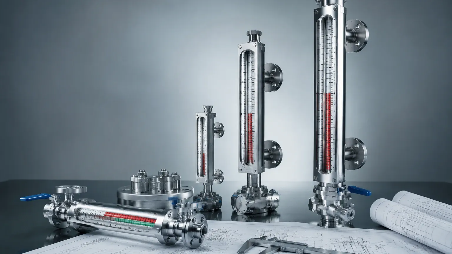
Magnetic level gauges utilize a more complex but highly robust principle. A bypass chamber is mounted to the side of the vessel. Inside this chamber is a float containing a high-intensity permanent magnet. As the liquid level in the tank rises or falls, the float moves accordingly. Outside the chamber, an indication rail (consisting of magnetic flaps or rollers) is mounted. The magnetic field from the float penetrates the chamber wall—which is made of non-magnetic material like 316 Stainless Steel—and rotates the flaps.
Typically, these flaps are bi-colored (e.g., red and white). As the float passes, the flaps flip to show one color below the liquid level and another above it. This creates a clear, high-contrast visual that can be read from a significant distance without the need for a direct view of the liquid itself.
Key Selection Criteria for Gauges L
Choosing the right gauge requires a systematic evaluation of the application's physical and chemical parameters. The following table provides a comparison of the primary types of Gauges L used in modern processing plants.
Comparison Table: Level Gauge Types
| Feature | Magnetic Level Gauges | Reflex Glass Gauges | Transparent Glass Gauges |
| :— | :— | :— | :— |
| Visibility | High (Bi-color flaps) | Moderate (Prismatic effect) | Moderate (Direct view) |
| Pressure Range | Up to 420 bar (42 MPa) | Up to 250 bar (25 MPa) | Up to 250 bar (25 MPa) |
| Temperature Range | -196°C to +450°C | -20°C to +400°C | -20°C to +400°C |
| Media Compatibility | Excellent (Hazardous/Toxic) | Good (Non-corrosive) | Good (Interface tracking) |
| Maintenance | Low (No glass to clean) | Moderate (Glass cleaning) | Moderate (Glass cleaning) |
| Redundancy | Can add reed switches/transmitters | Manual only | Manual only |
Application Suitability
* Magnetic Gauges: Ideal for high-pressure, high-temperature, or toxic media where glass breakage would pose a catastrophic risk. Since the liquid is completely contained within a metal pressure vessel, there is no risk of leakage through a sight window.
* Reflex Gauges: Best for clean, low-viscosity liquids. They use light refraction to make the liquid appear dark and the gas space appear light, providing a sharp contrast.
* Transparent Gauges: Necessary when the color of the liquid needs to be observed or when monitoring the interface between two different liquids (e.g., oil and water).
Technical Specifications and Material Considerations
The durability of Gauges L depends heavily on material selection. The wetted parts must withstand the corrosive nature of the process fluid while the external components must survive the ambient environment.
Chamber Materials
Standard chambers are typically constructed from 316L Stainless Steel due to its excellent corrosion resistance and non-magnetic properties. For more aggressive environments, specialty materials such as Titanium, Hastelloy, or plastics like PVC and PVDF are utilized. In the case of plastic gauges, the pressure and temperature ratings are significantly lower, usually limited to 6 bar (0.6 MPa) and 60°C to 100°C.
Float Design
The float is the most critical component of a magnetic level gauge. It must be engineered to match the specific gravity (SG) of the liquid. If the float is too heavy, it will sink; if it is too light, it may not submerge enough to align the magnets with the indication rail. Engineers must confirm the minimum and maximum operating SG before ordering. For high-pressure applications, floats are often pressurized or made from high-strength alloys to prevent collapsing.
Indication Rails
Indication rails are usually housed in a hermetically sealed glass or polycarbonate tube to protect the flaps from dust, moisture, and UV degradation. For offshore or highly corrosive environments, 316 Stainless Steel housings for the indication rail are recommended to prevent salt-spray damage.
Installation Guidelines and Best Practices
Proper installation of Gauges L ensures accurate readings and extends the service life of the instrument. Failure to follow these guidelines can result in float jamming or inaccurate level representation.
1. Vertical Alignment: The gauge must be installed perfectly vertical. A tilt of even a few degrees can cause the float to rub against the chamber walls, leading to friction that prevents smooth movement.
2. Bypass Piping: Ensure the connection sizes (e.g., DN20, DN25, or 1" NPT) match the tank nozzles. It is standard practice to install isolation valves between the tank and the gauge to allow for maintenance without draining the entire vessel.
3. Venting and Draining: Every gauge should be equipped with a vent valve at the top and a drain valve at the bottom. This allows for the safe removal of trapped gas during startup and the flushing of sediment during maintenance.
4. Magnetic Interference: Keep the gauge away from large motors, high-voltage cables, or other sources of strong electromagnetic fields, as these can interfere with the magnetic coupling between the float and the indication rail.
5. Insulation: In high-temperature applications, the chamber may need to be insulated to protect personnel. However, the indication rail itself must remain visible and should not be covered by insulation that could melt or trap excessive heat against the flaps.
Limitations and Operational Risks
While Gauges L are highly reliable, they are not universal solutions. Engineers must be aware of their technical boundaries:
* Viscosity and Solids: Highly viscous liquids or those containing large amounts of suspended solids can impede float movement. In such cases, a large-bore chamber or a specialized non-stick coating may be required.
* Coating and Scaling: If the process media tends to crystallize or leave deposits, the internal walls of the chamber and the float can become coated. This increases the weight of the float and can eventually cause it to stick. Regular flushing via the drain valve is necessary in these applications.
* Extreme Vibration: In applications with heavy mechanical vibration (e.g., near large reciprocating pumps), the magnetic flaps may shift position erroneously. High-stability magnetic rollers or dampening mounts can mitigate this risk.
* Flash Vaporization: Rapid changes in pressure can cause the liquid in the chamber to boil or "flash." The resulting turbulence can damage the float or cause it to jump, leading to temporary loss of level indication.
Frequently Asked Questions (FAQs)
Q: Can Gauges L be used for interface measurement?
A: Yes. By specifically weighting the float to sink in the upper (lighter) liquid but float on the lower (heavier) liquid, magnetic level gauges can accurately track the interface between two immiscible fluids.
Q: What is the maximum length for a single-piece level gauge?
A: While standard lengths often range up to 6 meters (approx. 20 feet), longer gauges can be manufactured. However, for lengths exceeding 3 meters, support brackets are usually required to ensure structural stability and maintain vertical alignment.
Q: Do magnetic level gauges require power?
A: The basic visual indication is entirely mechanical and requires no power. However, if you add a reed switch for point level alarms or a magnetostrictive transmitter for a 4-20mA signal, those components will require an external power supply.
Q: How do I choose between a reflex and a magnetic gauge?
A: Choose a reflex gauge for simple, low-cost visual checks of clean liquids. Choose a magnetic gauge if the liquid is hazardous, if you need to read the level from a distance, or if you require electronic integration (transmitters/switches) alongside local indication.
For more detailed technical data and customized configurations, project managers should Review product options and application support to ensure the selected Gauges L meet the specific safety and performance standards of their facility.