H Gauges
H Gauges
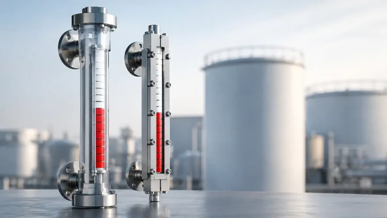
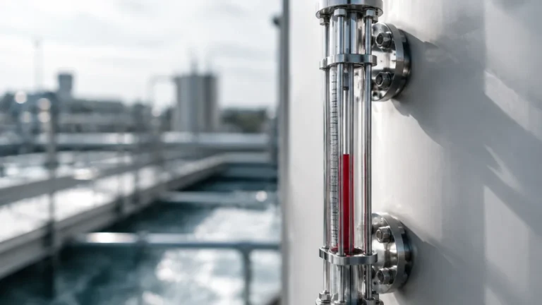
In the field of industrial process control, the term "H gauges" typically refers to instruments designed to measure and display the height (H) of a liquid within a vessel or tank. While electronic sensors provide data to control rooms, local level gauges remain indispensable for onsite verification, safety redundancy, and manual monitoring. These instruments, primarily categorized under Magnetic & Local Level Gauges, provide a direct or magnetically coupled visual representation of the fluid level without requiring external power.
Accurate height measurement is critical for inventory management, overfill prevention, and ensuring the steady state of chemical reactions. Understanding the mechanics, selection criteria, and installation requirements of these gauges is essential for plant engineers and maintenance professionals.
Measurement Principles: How Local Level Gauges Determine Liquid Height
Before selecting an H gauge, it is vital to understand the physics governing its operation. Most local level indicators rely on two fundamental principles: Hydrostatics and Buoyancy.
The Principle of Buoyancy (Archimedes' Principle)
In magnetic level gauges, a float is engineered to have a density lower than the process liquid. This float resides inside a bypass chamber connected to the vessel. As the liquid level in the tank changes, the liquid level in the bypass chamber follows suit (based on the principle of communicating vessels). The float moves up and down with the liquid surface. Inside the float is a high-intensity permanent magnet. This magnet acts through the wall of the non-magnetic chamber (usually stainless steel) to flip external magnetic flaps or move a follower, providing a visual indication of the "H" value.
The Principle of Communicating Vessels
This is the simplest form of height measurement used in glass or tubular H gauges. Two points on a tank—one near the bottom and one near the top—are connected to a vertical transparent tube. Gravity ensures the liquid level in the tube is identical to the level in the tank. The operator reads the height directly against a graduated scale.
Hydrostatic Pressure
While less common for purely "local visual" gauges, some H gauges utilize a diaphragm and a mechanical pointer to translate the pressure at the bottom of the tank into a height reading. The formula $P = \rho \cdot g \cdot h$ (where $P$ is pressure, $\rho$ is density, $g$ is gravity, and $h$ is height) allows the gauge to display the level based on the weight of the liquid column.
Types of H Gauges and Their Applications
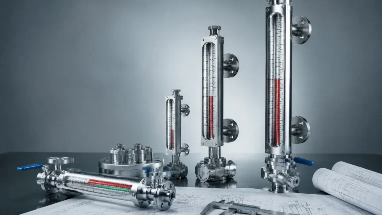
Choosing the correct gauge depends on the chemical compatibility, pressure, and temperature of the process. Below are the primary types of Magnetic & Local Level Gauges used in modern industry.
1. Magnetic Level Gauges (MLG)
MLGs are the most robust choice for hazardous or high-pressure environments. Because the process fluid is entirely contained within a pressure-sealed metal chamber, there is no risk of glass breakage or leakage of toxic fumes. They are widely used in oil and gas, chemical processing, and high-pressure steam boilers.
2. Reflex Glass Gauges
Reflex gauges use a prism-shaped glass window. The light entering the gauge is either absorbed or reflected depending on whether it hits liquid or gas. This creates a sharp contrast (usually dark for liquid and light for gas), making it easy to read the height from a distance.
3. Transparent Glass Gauges
These feature two plates of glass with the liquid in between. They are preferred when the color or clarity of the liquid must be observed, or for interface measurement (e.g., the boundary between oil and water).
4. Tubular Level Gauges
The most economical option, consisting of a clear tube protected by a metal guard. These are restricted to low-pressure, non-hazardous applications like water storage tanks or lubricant reservoirs.
Technical Selection Criteria for H Gauges
When specifying an H gauge, engineers must define several parameters to ensure the instrument survives the process environment and provides accurate data.
The "H" Dimension (Center-to-Center)
The most critical physical dimension is the "H" value, often denoted as the Center-to-Center (C-C) distance. This is the vertical distance between the center of the top process connection and the center of the bottom process connection.
* Visible Length: This is often slightly less than the C-C distance due to the mechanics of the float or the gauge frame.
* Blind Spots: Every H gauge has a "dead zone" at the top and bottom where the float cannot travel or the glass is obscured. These must be accounted for in tank design.
Material Compatibility
The chamber and float materials must be resistant to the process media. Common materials include:
* 304/316L Stainless Steel: Standard for water and general chemicals.
* PTFE/PFA Lining: Required for highly corrosive acids like hydrochloric or sulfuric acid.
* Titanium or Hastelloy: Used for extreme temperatures and aggressive saline environments.
Pressure and Temperature Ratings
Standard H gauges typically handle pressures from vacuum up to 40 bar (4.0 MPa), but high-pressure variants can exceed 320 bar. Temperature ratings range from cryogenic levels (-196°C) to superheated steam applications (+450°C).
Practical Selection Table
| Feature | Magnetic Level Gauge | Reflex Glass Gauge | Tubular Gauge |
| :— | :— | :— | :— |
| Max Pressure | Up to 400 bar | Up to 250 bar | Up to 10 bar |
| Max Temperature | Up to 500°C | Up to 400°C | Up to 100°C |
| Visibility | Excellent (Flaps/Flags) | Good (Contrast) | Moderate (Clear) |
| Hazardous Media | Best (Total Containment) | Moderate | Low (Risk of Breakage) |
| Maintenance | Low | Moderate | High |
| Cost | High | Moderate | Low |
Installation Considerations
Correct installation is paramount for the safety and accuracy of H gauges. Failure to follow these guidelines can result in float jamming or structural failure.
1. Vertical Alignment: The gauge must be installed perfectly vertical. A tilt of even a few degrees can cause the internal float to rub against the chamber walls, leading to friction and inaccurate readings.
2. Support Brackets: For gauges with a height (H) exceeding 3 meters (3000 mm), intermediate support brackets are required to prevent vibration and mechanical stress on the process flanges.
3. Venting and Draining: Always install a vent valve at the top and a drain valve at the bottom. This allows for safe depressurization and cleaning of the chamber without removing the entire unit from the tank.
4. Magnetic Interference: For magnetic H gauges, ensure that no large ferrous structures or high-voltage cables are located within 200 mm of the chamber, as these can interfere with the magnetic coupling.
5. Isolation Valves: Install high-quality isolation valves between the tank and the gauge. This allows the gauge to be serviced while the tank remains in operation.
Operational Limitations and Risks
While highly reliable, H gauges have specific limitations that operators must acknowledge:
* Magnetic Particles: In magnetic gauges, if the process fluid contains iron filings or magnetic scale, these particles will adhere to the float's magnet, eventually weighing it down or causing it to stick. Magnetic filters (traps) should be installed in these cases.
* Viscosity: High-viscosity liquids (typically above 500 cP) can impede the movement of the float. For such applications, oversized chambers or special float designs are necessary.
* Specific Gravity Fluctuations: Since the float is designed for a specific liquid density, a significant change in the fluid composition (e.g., switching from oil to water) will change the buoyancy depth of the float, leading to an offset in the height reading.
* Scaling and Coating: In glass gauges, fluids that leave a residue or scale will quickly obscure the visibility, requiring frequent cleaning.
Maintenance and Troubleshooting Guide
To ensure a long service life, a routine maintenance schedule should be implemented.
Routine Inspection
* Check for leaks at the flanges and gaskets.
* Verify that the magnetic flaps are clean and moving freely.
* Inspect glass gauges for any signs of clouding or erosion (thinning of the glass), especially in steam service.
Troubleshooting Common Issues
* Float is Stuck: This is often caused by debris or the float being crushed by a pressure surge. Close the isolation valves, drain the chamber, and inspect the float. Ensure the float hasn't taken on liquid (leaked).
* Inaccurate Reading: Verify the liquid density matches the float's design specification. Check for magnetic interference from nearby equipment.
* Flaps Not Flipping: The magnet inside the float may have lost its strength due to exposure to temperatures exceeding its Curie point. This requires float replacement.
Frequently Asked Questions (FAQs)
Q: Can an H gauge be used for interface measurement?
A: Yes. By weighting the float to a specific density that falls between the densities of the two liquids (e.g., 0.8 g/cm³ for an oil-water interface), the float will sink through the top layer and float on the bottom layer.
Q: What is the maximum height (H) available?
A: While individual sections are typically limited to 6 meters for shipping, magnetic level gauges can be joined with flanges to reach heights of 12 meters or more. However, external support is mandatory for these lengths.
Q: Do these gauges require calibration?
A: Mechanical H gauges do not require calibration in the traditional sense, as they rely on physical laws. However, if a reed chain transmitter or magnetostrictive sensor is attached to the side for remote signaling, that electronic component will require periodic calibration.
Conclusion
H gauges serve as the primary "eyes" on the ground for industrial tank management. Whether utilizing the direct visibility of a glass gauge or the robust containment of a magnetic level indicator, selecting the right instrument requires a deep understanding of the process height, fluid properties, and safety requirements. By adhering to strict installation standards and performing regular maintenance, these instruments provide decades of reliable service in the most demanding environments. For those looking to integrate these solutions into their systems, exploring the options within Magnetic & Local Level Gauges is the first step toward achieving precise and safe level control.