Conductive Level Sensors
Conductive Level Sensors
Conductive level sensors represent one of the most reliable and cost-effective methods for point level detection in conductive liquids. Often utilized in industrial automation and process control, these instruments provide a straightforward solution for overflow prevention, pump control, and dry-run protection. Unlike continuous measurement technologies like radar or ultrasonic sensors, conductive sensors function as switches, identifying whether a liquid has reached a specific height within a vessel.
For engineers and plant operators, understanding the underlying physics and the specific environmental constraints of conductive technology is essential for ensuring long-term system stability. This guide explores the principles, selection criteria, and installation best practices for conductive level measurement systems.
Measurement Principles
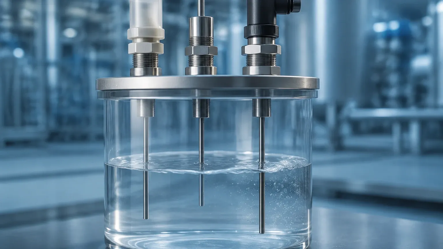
The operation of a conductive level sensor is based on the electrical conductivity of the process medium. The system typically consists of a low-voltage power source, a control relay, and one or more electrodes (probes) inserted into the tank.
The Electrical Circuit
When the liquid level rises and touches the electrode, it completes an electrical circuit between the probe and a reference point. This reference point can be the metallic wall of the tank or a separate ground electrode (often called the "base" or "common" probe) in non-conductive or plastic vessels. The control unit detects the resulting current flow and triggers a relay output to signal a high or low level.
AC vs. DC Current
A critical technical distinction in conductive sensors is the use of Alternating Current (AC). High-quality industrial conductive level sensors utilize a low-voltage AC signal rather than Direct Current (DC). The use of DC would lead to electrolysis, causing the rapid degradation of the electrodes and the buildup of ions in the liquid, which can contaminate the process. AC prevents these chemical reactions, ensuring the longevity of the probes and maintaining the purity of the medium.
Sensitivity Adjustment
Not all liquids conduct electricity equally. The control relay usually features an adjustable sensitivity setting (measured in kΩ). This allows the sensor to be tuned to the specific conductivity of the medium, ensuring that the system can distinguish between the actual liquid level and residual moisture or foam on the probes.
System Components and Design
A complete conductive level system is comprised of three primary elements: the electrodes, the probe head, and the controller.
1. Electrodes (Probes)
Electrodes are typically stainless steel (SS316L) rods, though specialized materials like Titanium, Hastelloy, or Tantalum are used for highly corrosive chemicals. For deep tanks, wire-rope electrodes may be used instead of rigid rods. Often, the rods are coated with an insulating material (such as Polyolefin or PTFE) except for the very tip, which prevents false triggering if the rods touch or if there is heavy condensation.
2. The Probe Head
The head houses the electrical connections and provides the process connection (threaded or flanged). It must be rated for the appropriate environmental conditions, often requiring IP65 or higher ingress protection to withstand wash-downs or outdoor exposure.
3. The Control Relay
The relay is the "brain" of the system. It is usually mounted in a control cabinet on a DIN rail. It processes the signal from the probes and provides the switching output (SPDT or DPDT). Many controllers include a time-delay feature to prevent "chattering" caused by turbulent liquid surfaces.
Practical Selection Criteria
Selecting the right conductive level sensor requires a detailed analysis of the liquid properties and the vessel environment. Use the following table as a baseline for determining if your media is suitable for conductive detection.
Table 1: Typical Conductivity of Common Media
| Medium | Conductivity (μS/cm) | Suitability |
| :— | :— | :— |
| Deionized Water | < 1 | Unsuitable |
| Distilled Water | 0.5 – 5 | Marginal (Requires high sensitivity) |
| Tap Water | 50 – 800 | Excellent |
| Wastewater | 500 – 5,000 | Excellent |
| Beer / Fruit Juice | 1,000 – 3,000 | Excellent |
| Strong Acids/Bases | > 10,000 | Excellent (Requires chemical-resistant probes) |
| Hydrocarbons (Oil/Diesel) | ~0 | Unsuitable |
Key Evaluation Factors
* Number of Points: Do you need a single point (high level) or multiple points (pump start/stop)? Multi-rod probes can support up to five or more switching points in a single process connection.
* Process Temperature: Standard probes handle up to 100°C, but specialized ceramic-insulated probes can withstand much higher temperatures in steam applications.
* Process Pressure: Ensure the probe head and seals are rated for the tank's maximum operating pressure (e.g., 10 bar or 16 bar).
* Chemical Compatibility: Match the electrode and gasket materials (EPDM, FKM) to the chemical composition of the liquid.
Installation Considerations
Proper installation is vital to prevent false readings and mechanical failure. Engineers should follow these guidelines during the design and commissioning phases:
1. Avoid Turbulence: Do not install probes directly under a fill pipe. The falling liquid can cause false triggering. If turbulence is unavoidable, use a stilling well (a perforated pipe) to shield the electrodes.
2. Electrode Spacing: In multi-rod configurations, ensure the rods are spaced far enough apart to prevent bridging by bubbles or debris. Spacers (insulators) should be used for rods longer than 1000 mm.
3. Grounding: In plastic or lined tanks, a reference (common) probe must be installed. This probe must reach deeper than the lowest switching probe to ensure the circuit can always be completed.
4. Mounting Position: While vertical mounting is standard, some conductive sensors can be mounted horizontally. However, horizontal mounting is more susceptible to buildup and coating issues.
5. Wiring: Use shielded cable for long runs between the probe head and the controller to prevent electromagnetic interference (EMI) from inducing a current that the relay might interpret as a level signal.
Applications in Industry
Conductive level sensors are ubiquitous in sectors where water-based or conductive chemicals are handled. For more complex measurement needs, including continuous monitoring, professionals often refer to the Main Page of industrial instrument suppliers to compare conductive switches with radar or ultrasonic alternatives.
* Water Treatment: Controlling levels in sumps, storage tanks, and dosing tanks for alum or chlorine.
* Food & Beverage: Detecting levels in milk tanks, brewing kettles, and carbonated beverage fillers (where the sensor must be food-grade and CIP-capable).
* Boiler Control: Monitoring low-water conditions in steam boilers to prevent dry-firing.
* Chemical Processing: Managing levels in neutralization tanks where acids and bases are mixed.
Limitations and Common Risks
While robust, conductive level sensors are not universal solutions. The following limitations must be considered:
* Non-Conductive Liquids: These sensors will not work with oils, fats, pure alcohols, or ultra-pure water. For these applications, float switches or capacitive sensors are preferred.
* Coating and Fouling: If the liquid is highly viscous or prone to leaving a conductive film (like some slurries), the sensor may stay "on" even after the level drops. This is known as "bridging."
* Foam: Depending on the sensitivity setting, foam can trigger the sensor. If foam detection is not desired, the sensitivity must be lowered, or a different technology (like a vibration fork) should be used.
* Electrode Corrosion: Even with AC current, harsh chemicals can eventually pit or corrode the electrodes, increasing resistance and leading to failure.
Comparison with Other Technologies
To help in the selection process, the following table compares conductive sensors with other common point-level technologies.
Table 2: Point Level Technology Comparison
| Feature | Conductive Sensor | Float Switch | Vibration (Tuning Fork) |
| :— | :— | :— | :— |
| Moving Parts | None | Yes | None |
| Media Type | Conductive liquids only | Most liquids | Liquids or Solids |
| Viscosity Limit | Low to Medium | Low | High |
| Build-up Resistance | Moderate | Poor | High |
| Cost | Low | Low | Moderate |
| Maintenance | Low | Moderate | Low |
Frequently Asked Questions (FAQ)
Q: Can I cut the electrodes to length on-site?
A: Yes, most rigid rod conductive probes are designed to be cut to the exact length required during installation. However, ensure that any insulation removed is replaced correctly and that the rod ends are deburred.
Q: Why is my sensor triggering when the tank is empty?
A: This is usually due to moisture or residue buildup on the probe head or the insulators between the rods. Cleaning the insulators and adjusting the sensitivity on the control relay typically resolves this.
Q: Is there a maximum distance between the probe and the controller?
A: Yes, typically the limit is between 100 and 300 meters, depending on the cable capacitance and the sensitivity of the controller. For very long distances, a transmitter with a 4-20mA or digital output may be more appropriate.
Q: Can these be used in hazardous (Ex) areas?
A: Yes, but they must be used with an intrinsically safe (IS) barrier or an Ex-rated control relay that limits the energy sent to the probes in the hazardous zone.
Conclusion
Conductive level sensors remain a staple in industrial process control due to their simplicity and reliability. By understanding the conductivity requirements of the medium and ensuring a proper mechanical installation, engineers can implement a level control system that requires minimal maintenance over many years of service. When faced with non-conductive media or requirements for continuous level data, it is advisable to consult a comprehensive technical resource or the Main Page of a specialized manufacturer to explore the full range of available measurement technologies.