Navega
Navega
In the complex landscape of industrial automation, the ability to accurately monitor and control liquid or solid levels is a fundamental requirement for operational safety and efficiency. To "navega" or navigate the myriad of technical specifications, environmental constraints, and technological options requires a structured engineering approach. Choosing the wrong instrumentation can lead to costly downtime, safety hazards, or product waste. This guide provides a comprehensive technical overview of modern level measurement technologies, serving as a roadmap for engineers to navigate the selection and implementation process effectively.
For those beginning their search for specific hardware, visiting our Main Page offers a gateway to detailed product specifications and application-specific support.
Fundamental Principles of Level Measurement
Before selecting a device, it is essential to understand the physics governing different measurement methods. Industrial level sensors generally fall into two categories: continuous measurement and point level detection.
1. Radar Level Measurement (Non-Contact)
Radar level meters operate on the Time-of-Flight (ToF) principle. The device emits high-frequency electromagnetic pulses (typically in the 26 GHz or 80 GHz range). These pulses travel at the speed of light, reflect off the surface of the medium, and return to the sensor. The distance is calculated based on the time delay between transmission and reception.
* FMCW (Frequency Modulated Continuous Wave): Modern high-end radar units often use FMCW, which transmits a continuous signal with a constantly changing frequency. The difference in frequency between the transmitted and received signal is directly proportional to the distance.
* Advantages: Radar is largely unaffected by temperature, pressure, or vacuum conditions. It can penetrate vapor and dust, making it the gold standard for volatile or high-pressure environments.
2. Ultrasonic Level Measurement
Similar to radar, ultrasonic sensors use the ToF principle but utilize sound waves instead of electromagnetic waves. The sensor emits an ultrasonic pulse (typically 20 kHz to 70 kHz) that reflects off the product surface.
* Speed of Sound: Unlike radar, the speed of sound is highly dependent on the air temperature and gas composition. Most ultrasonic sensors include an integrated temperature sensor to compensate for these changes.
* Limitations: Ultrasonic waves cannot travel through a vacuum and are easily scattered by heavy foam or extreme turbulence.
3. Hydrostatic Level Measurement
This contact-based method relies on the relationship between the height of a liquid column and the pressure it exerts at the base of the tank. The formula $P = \rho \cdot g \cdot h$ (where $P$ is pressure, $\rho$ is density, $g$ is gravity, and $h$ is height) is used to derive the level.
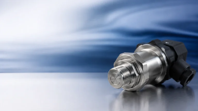
* Implementation: A pressure transmitter is mounted at the bottom of the tank or suspended via a cable (submersible type).
* Consideration: This method requires a constant or known density of the medium. If the liquid density changes significantly due to temperature or concentration, the level reading will drift.
4. Magnetic Level Gauges
Magnetic level gauges are used for visual indication and can be equipped with transmitters for remote monitoring. They consist of a bypass chamber connected to the side of a vessel. Inside the chamber, a float containing a permanent magnet moves with the liquid level. Outside the chamber, a series of magnetic flaps or a reed-chain transmitter reacts to the float’s position.
Navigating Selection Criteria: The Navega Framework
To successfully navega the selection process, engineers must evaluate the application against five core dimensions: Media Properties, Process Environment, Tank Geometry, Accuracy Requirements, and Maintenance Constraints.
Media Properties
* Dielectric Constant ($ε_r$): For radar measurement, the reflectivity of the surface depends on the dielectric constant. Low $ε_r$ fluids (like hydrocarbons) reflect less energy than high $ε_r$ fluids (like water).
* Corrosiveness: Highly acidic or alkaline media require specialized materials such as PTFE (Teflon), PVDF, or high-grade stainless steel (316L).
* Viscosity and Coating: Sticky media can cause build-up on contact sensors, leading to "false high" readings. Non-contact radar is often preferred here.
Process Environment
* Temperature and Pressure: Standard ultrasonic sensors are limited to approximately 2 bar and 80°C. In contrast, high-frequency radar can handle temperatures exceeding 400°C and pressures up to 160 bar.
* Agitation and Foam: If a tank has heavy agitators or thick foam, non-contact radar with advanced signal processing or a guided wave radar (GWR) might be necessary to ensure signal stability.
Practical Selection Table for Industrial Applications
The following table provides a quick reference to navega the initial technology choice based on common industrial scenarios.
| Application Scenario | Recommended Technology | Primary Reason |
| :— | :— | :— |
| Open Water Reservoirs | Ultrasonic | Cost-effective, non-contact, reliable for water. |
| Chemical Storage (Corrosive) | 80GHz Radar (PTFE Lens) | High chemical resistance, non-contact. |
| High-Pressure Steam Boilers | Guided Wave Radar | Unaffected by steam and high pressure. |
| Deep Wells / Boreholes | Hydrostatic (Submersible) | Simple installation in narrow pipes. |
| Small Process Tanks (Agitated) | 80GHz Radar | Narrow beam angle avoids internal obstructions. |
| Visual Indication (Bypass) | Magnetic Level Gauge | No power required for local display. |
Installation Considerations and Best Practices
Even the most advanced sensor will fail if installed incorrectly. When you navega the installation phase, keep these engineering guidelines in mind:
1. Blocking Distance (Dead Zone): Every ultrasonic and radar sensor has a "dead zone" directly beneath the sensor face where measurement is impossible. Ensure the sensor is mounted high enough that the maximum liquid level never enters this zone.
2. Nozzle Dimensions: For radar and ultrasonic units, the mounting nozzle should be as short and wide as possible. Long, narrow nozzles can create internal reflections (ringing) that interfere with the actual level signal.
3. Avoid Obstructions: Do not mount sensors directly above ladders, heating coils, or inflow pipes. These objects create "false echoes." Modern sensors allow for "False Signal Suppression" or "Echo Mapping," where the sensor is taught to ignore these static reflections.
4. Positioning: Sensors should generally be mounted at 1/6th to 1/4th of the tank diameter from the wall. Mounting too close to the center can cause multiple reflections in domed-roof tanks, while mounting too close to the wall can cause interference from the tank shell.

Common Risks and Limitations
While modern instrumentation is robust, certain conditions present ongoing risks to accuracy:
* Vapor Layers: In chemical processing, heavy vapor layers can change the propagation speed of ultrasonic waves, leading to significant errors. Radar is the preferred alternative as electromagnetic waves are not affected by gas composition.
* Heavy Foam: Foam can act as an absorber for both sound and radio waves. In cases of extremely thick foam, a hydrostatic transmitter or a displacement-based sensor may be the only viable options.
* Build-up and Scaling: In wastewater or mining slurries, material can build up on the sensor face. While some radar sensors can "see through" thin layers of build-up, heavy scaling will eventually require manual cleaning or the use of a purging system.
Frequently Asked Questions (FAQ)
Q: How does 80 GHz radar differ from 26 GHz radar?
A: 80 GHz radar has a much narrower beam angle (often as small as 3°) compared to 26 GHz (typically 8°-10°). This allows the 80 GHz unit to avoid internal tank obstructions more easily and provides better resolution in small vessels.
Q: Can I use an ultrasonic sensor in a vacuum tank?
A: No. Ultrasonic sensors require a medium (usually air or gas) to transmit sound waves. In a vacuum, there is no medium to carry the sound, so the sensor will not function. Radar is required for vacuum applications.
Q: Is hydrostatic measurement affected by tank shape?
A: No. Hydrostatic pressure depends only on the height and density of the liquid column, not the volume or shape of the tank. This makes it very versatile for irregularly shaped vessels.
Q: What is the maintenance cycle for these instruments?
A: Non-contact sensors like radar and ultrasonic units are virtually maintenance-free unless there is significant build-up on the lens. Contact sensors like magnetic floats or hydrostatic diaphragms should be inspected annually for scaling or mechanical wear.
Conclusion
Successfully navigating the world of level measurement requires a balance between understanding the physical properties of the process and the technical limitations of the available sensors. By following a structured "navega" approach—evaluating media, environment, and geometry—engineers can select a solution that provides long-term reliability and accuracy.
For further technical documentation, CAD drawings, or to consult with an application engineer regarding your specific project requirements, please refer to the resources available on our Main Page. Selecting the right instrument is the first step toward a more efficient and safer industrial process.