Industrial Water Sensor
Industrial Water Sensor
In modern industrial automation, the term "industrial water sensor" encompasses a broad range of technologies designed to monitor level, flow, and quality within complex water management systems. For process engineers and facility managers, selecting the correct sensor is not merely a matter of measuring a liquid; it is about ensuring system reliability, preventing environmental non-compliance, and optimizing resource consumption. Whether managing municipal wastewater, cooling towers, or high-purity process water, understanding the underlying physics of measurement is the first step toward a successful installation.
Industrial water sensors serve as the primary data source for PLC (Programmable Logic Controller) and SCADA systems. By converting physical properties into electrical signals—typically 4-20mA, RS485 Modbus, or HART protocols—these instruments allow for real-time decision-making in critical infrastructures.
Core Measurement Principles
Before selecting a specific model, it is essential to understand the principles that govern how an industrial water sensor detects the presence or level of a medium. Most industrial applications utilize one of the following four methodologies.
Hydrostatic Pressure
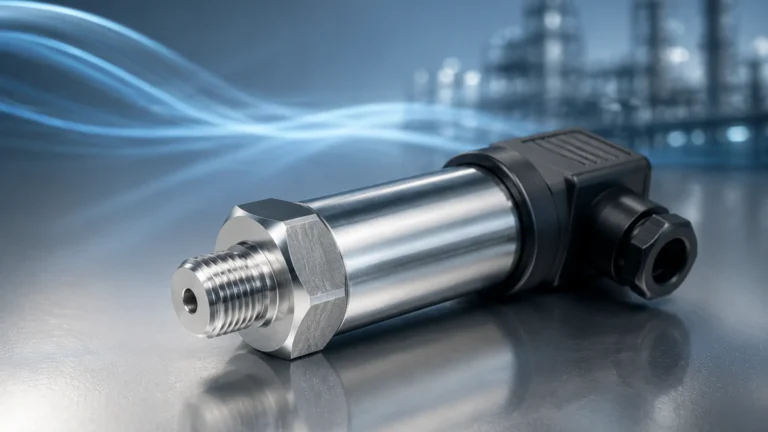
Hydrostatic level sensors operate on the principle that the pressure at a specific point in a static liquid is proportional to the height of the liquid column above it. The formula used is $P = \rho gh$, where $P$ is pressure, $\rho$ is the density of the water, $g$ is gravity, and $h$ is the height of the liquid.
These sensors are typically submersible or externally mounted at the bottom of a tank. They are highly effective for deep wells, reservoirs, and vented tanks where the water density remains relatively constant. However, because they rely on pressure, changes in atmospheric pressure (if the tank is sealed) or significant temperature-induced density changes can affect accuracy.
Ultrasonic Time-of-Flight
Ultrasonic sensors are non-contact devices that emit high-frequency sound waves (typically 20 kHz to 200 kHz). The sensor measures the time it takes for the sound pulse to travel to the water surface and reflect back to the transducer. Since the speed of sound in air is known, the distance to the water can be calculated.
Ultrasonic technology is favored for its ease of installation and lack of moving parts. It is ideal for open channels and wastewater pits. Its primary limitation is its sensitivity to air temperature fluctuations, heavy foam, and surface turbulence, all of which can scatter or absorb the sound signal.
Radar (Microwave) Technology
Radar sensors, specifically Frequency Modulated Continuous Wave (FMCW) or Pulse Radar, use electromagnetic waves instead of sound. These waves travel at the speed of light and are largely unaffected by air temperature, pressure, or vacuum conditions.
Radar is considered the gold standard for high-precision industrial water sensing. It can penetrate steam and vapor, making it suitable for boiler feed water or chemical mixing tanks. While more expensive than ultrasonic sensors, the long-term reliability and accuracy (often within ±2mm) justify the investment in critical process environments.
Capacitance and Conductivity
Conductivity sensors utilize the electrical properties of water to detect levels. When water touches a probe, it completes an electrical circuit, triggering a switch. Capacitance sensors measure the change in electrical capacitance between two electrodes (or one electrode and the tank wall) as the water level rises. These are often used for point-level detection (high/low alarms) rather than continuous measurement.
Selection Criteria for Industrial Water Sensors
Choosing the right technology requires a detailed analysis of the application environment. The table below provides a comparison of the most common technologies used in industrial water management.
| Technology | Contact Type | Accuracy | Best For | Limitations |
| :— | :— | :— | :— | :— |
| Hydrostatic | Contact | High (0.1% – 0.5%) | Deep wells, vented tanks, reservoirs | Sensitive to density changes |
| Ultrasonic | Non-contact | Moderate (0.25%) | Open channels, wastewater, sumps | Affected by foam, steam, and wind |
| Radar | Non-contact | Very High (±2mm) | Process tanks, high temperature/pressure | Higher initial cost |
| Magnetic Gauge | Contact | High | Visual monitoring, high-pressure boilers | Requires bypass pipe installation |
| Level Switch | Contact | N/A (Point level) | Overfill protection, pump control | No continuous level data |
Application-Specific Considerations
Wastewater and Slurry Management
In wastewater treatment, an industrial water sensor must contend with suspended solids, grease, and biological growth. Non-contact sensors like ultrasonic or radar are preferred here to prevent sensor fouling. If using hydrostatic sensors, a "flush diaphragm" design is necessary to prevent the sensing element from clogging with debris.
High-Purity and Deionized Water
For pharmaceutical or semiconductor water treatment, the sensor must not contaminate the medium. Non-contact radar is ideal because it never touches the water. If a contact sensor is used, it must be constructed from 316L stainless steel or PTFE to ensure material compatibility and prevent leaching.
Cooling Towers and Outdoor Reservoirs
Outdoor installations face challenges from ambient temperature swings and sunlight. Ultrasonic sensors used outdoors must have integrated temperature compensation. Furthermore, in large reservoirs, the sensor should be protected from wind-induced waves using a stilling well—a vertical pipe that dampens surface movement to provide a steady reading.
Installation Guidelines and Best Practices
Proper installation is as critical as selecting the right sensor. Even the most advanced radar unit will fail if positioned incorrectly. For more detailed technical specifications and product variations, engineers should consult the Main Page of the equipment manufacturer to ensure compatibility with existing mounting flanges.
1. Avoid the "Dead Zone": Every non-contact sensor has a "blocking distance" or dead zone directly beneath the transducer (typically 0.1m to 0.5m or 4" to 20"). The water level should never enter this zone, or the sensor will lose its signal. Mount the sensor high enough to account for the maximum possible water level.
2. Internal Obstructions: Ensure the sensor’s signal path is clear of ladders, pipes, or agitators. For radar and ultrasonic sensors, the "beam angle" determines the spread of the signal. If an obstruction is within the beam's path, it will create a false reflection.
3. Positioning Relative to Inflow: Never install a sensor directly above an inlet pipe. The turbulence and aeration from the incoming water will cause erratic readings and may physically damage contact-based sensors.
4. Cable Protection: For submersible hydrostatic sensors, the cable often contains a vent tube to compensate for atmospheric pressure. This tube must remain unkinked and dry. Using a junction box with a desiccant filter is a standard industry practice to prevent moisture from entering the vent tube.
Common Risks and Limitations
While industrial water sensors are robust, they are not infallible. Understanding the failure modes helps in designing redundant systems.
* Foam Interference: In many industrial processes, water can develop a layer of surface foam. Ultrasonic waves are often absorbed by foam, leading to a "Loss of Echo" error. Radar is more resistant but can still be attenuated by thick, dense foam. In these cases, a stilling well or a contact-based technology like a magnetic level gauge may be required.
* Vapor and Condensation: High-temperature water creates steam. Condensation on an ultrasonic transducer face can block the sound pulse. Many modern sensors, such as those produced by Welk, feature specialized antenna designs or "drip-off" surfaces to minimize the impact of moisture buildup.
* Chemical Compatibility: "Water" in an industrial context often contains acids, bases, or hydrocarbons. Ensure that the wetted materials of the sensor (e.g., PP, PVDF, or Stainless Steel) are rated for the specific chemical composition of the fluid.
Frequently Asked Questions (FAQ)
Q: What is the difference between a water level sensor and a water level transmitter?
A: A sensor is the component that detects the physical change, while a transmitter converts that change into a standardized electrical signal (like 4-20mA) for long-distance transmission. In modern industrial contexts, the terms are often used interchangeably because most devices integrate both functions into a single housing.
Q: How often should an industrial water sensor be calibrated?
A: For non-critical applications, an annual check is sufficient. However, in regulated industries like wastewater discharge or chemical processing, semi-annual or quarterly calibration against a manual reference (like a dip tape) is recommended to account for sensor drift or environmental changes.
Q: Can a radar sensor measure water through a plastic tank lid?
A: Yes. Certain radar frequencies can penetrate plastic or fiberglass tank tops, allowing for measurement without cutting a hole in the tank. This is particularly useful for sealed chemical storage tanks.
Pre-Purchase Checklist for Project Managers
Before finalizing a purchase or requesting a quote, confirm the following technical details to ensure the industrial water sensor meets the project requirements:
* Tank Geometry: What is the total height, diameter, and shape of the vessel? Is it open or closed?
* Medium Characteristics: Is it clean water, wastewater, or a chemical solution? What is the expected temperature and pressure range?
* Output Requirements: Does the control system require an analog signal (4-20mA), a digital protocol (Modbus/HART), or simple relay switches for pump control?
* Mounting Constraints: What is the available flange size or thread type (NPT/G)? Is there enough overhead clearance for the sensor body?
* Power Supply: Is 24V DC available at the installation site, or is a loop-powered device required?
By addressing these factors during the planning phase, engineering teams can implement a level measurement solution that minimizes maintenance and maximizes operational uptime. For a comprehensive overview of available technologies and customized OEM/ODM options, reviewing the Main Page of a dedicated manufacturer like Welk can provide the necessary technical clarity for complex industrial applications.