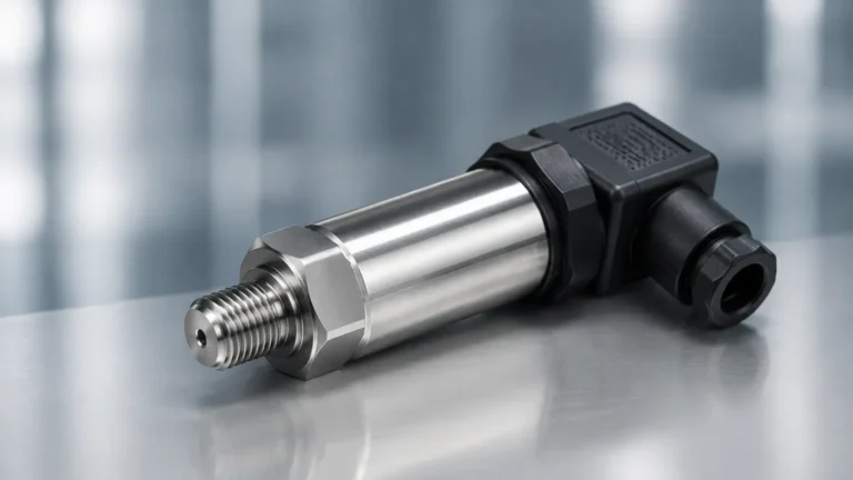
Capacitance Probes
Capacitance Probes
Capacitance probes represent one of the most versatile and established technologies in the field of industrial level measurement. Utilized across diverse sectors including water treatment, chemical processing, and oil and gas, these instruments provide reliable data for both point-level detection and continuous level monitoring. As a professional manufacturer, Welk designs these sensors to meet the rigorous demands of industrial automation, ensuring accuracy even in challenging environments characterized by high temperatures or corrosive media.
Understanding the technical nuances of capacitance probes is essential for process engineers and maintenance professionals. This guide details the underlying physical principles, selection criteria, installation best practices, and the limitations inherent to the technology to assist in optimal instrument specification.
Measurement Principles of Capacitance Probes
The operation of capacitance probes is based on the electrical principle of capacitance. A capacitor consists of two conductive plates separated by an insulating material known as a dielectric. In an industrial level measurement application, the probe (the electrode) acts as one plate of the capacitor, while the vessel wall (if metallic and conductive) serves as the second plate. If the tank is non-conductive, a reference ground rod or a concentric shield is used as the second plate.
The capacitance ($C$) of this system is defined by the formula:
$$C = \epsilon \cdot (A / d)$$
Where:
* $\epsilon$ (Epsilon): The dielectric constant (permittivity) of the material between the plates.
* A: The surface area of the plates.
* d: The distance between the plates.
In a level measurement scenario, the distance ($d$) and the area ($A$) remain constant. The variable factor is the dielectric constant of the medium between the probe and the tank wall. Air and gases typically have a dielectric constant of approximately 1.0. Most industrial liquids and solids have a significantly higher dielectric constant (e.g., mineral oil $\approx$ 2.0, plastic pellets $\approx$ 1.1–3.0, and water $\approx$ 80).
As the level of the medium rises, it displaces the air or gas surrounding the probe. Because the medium has a different dielectric constant than the air it replaces, the total capacitance of the system changes proportionally to the level. The electronics within the probe head convert this change in capacitance into an electrical signal, such as a 4-20 mA analog output for continuous measurement or a relay switch for point-level detection.
Conductive vs. Non-Conductive Media
The behavior of the probe changes based on the electrical conductivity of the process material:
1. Non-Conductive Media: For materials like oils or dry powders, the material acts as the dielectric. The probe is often a bare metal rod. The capacitance increases as the level rises because the dielectric constant of the material is higher than that of air.
2. Conductive Media: For materials like water or acids, the liquid acts as an extension of the ground plate rather than a dielectric. In these cases, the probe must be insulated with a material such as PTFE (Teflon) or PFA. The insulation itself becomes the dielectric. As the conductive liquid rises, it covers more of the insulated probe, effectively increasing the "area" of the capacitor and thus increasing capacitance.
Types of Capacitance Probes and Configurations
Capacitance probes are manufactured in various configurations to accommodate different vessel geometries and material characteristics. For a detailed overview of available hardware and technical support, users should consult the Main Page of the Welk industrial catalog.
Point Level Switches
These probes are designed to detect the presence or absence of material at a specific height. They are commonly used for high-level overfill protection or low-level pump protection. They are robust and often feature "active shield" technology to ignore material buildup on the probe.
Continuous Level Transmitters
These instruments provide a constant reading of the level throughout the height of the vessel. They are available as rigid rods for shorter tanks (typically up to 3 meters or 10 feet) or flexible cables for tall silos and deep wells (reaching up to 30 meters or 100 feet).
Probe Construction Materials
* Rod Probes: Usually made of 316 Stainless Steel. Used for liquids and some bulk solids in smaller vessels.
* Cable Probes: Used when the measurement range exceeds the practical length of a rigid rod or when the sensor must withstand the downward tensile forces of heavy bulk solids.
* Insulation: PTFE, PFA, or FEP are used for chemical resistance and to provide the dielectric layer for conductive liquids.
Technical Selection Criteria
Selecting the correct capacitance probe requires a thorough analysis of the process conditions. The following table provides a general comparison of selection factors:
| Factor | Requirement/Impact | Recommendation |
| :— | :— | :— |
| Dielectric Constant (dk) | Low dk (< 2.0) requires high sensitivity electronics. | Use a probe with a concentric shield to increase base capacitance. |
| Conductivity | Conductive liquids will short a bare probe. | Specify an insulated probe (PTFE/PFA coating). |
| Temperature | High temperatures can degrade insulation. | Use high-temperature ceramics or specialized cooling extensions. |
| Pressure | High pressure requires robust process seals. | Verify the pressure rating of the threaded or flanged connection. |
| Vessel Material | Non-metallic tanks (plastic/fiberglass) lack a ground plane. | Install a probe with an integrated ground rod or reference tube. |
| Material State | Bulk solids can exert high pull-down forces. | Use a heavy-duty cable probe with a reinforced mounting. |
Practical Selection Table for Common Media
| Medium | Dielectric Constant (Approx.) | Conductivity | Recommended Probe Type |
| :— | :— | :— | :— |
| Deionized Water | 80 | Low | Insulated Rod/Cable |
| Sulfuric Acid | 84 | High | PFA Insulated Rod |
| Diesel Fuel | 2.1 | Non-conductive | Bare or Insulated Rod |
| Cement Powder | 4.0 – 6.0 | Non-conductive | Heavy-duty Cable |
| Plastic Pellets | 1.2 – 2.5 | Non-conductive | Rod with Concentric Shield |
Installation Considerations
To ensure the accuracy of capacitance probes, specific installation protocols must be followed. Failure to account for vessel geometry and material flow can lead to erratic readings.
1. Avoid the Fill Stream: Probes should never be installed directly in the path of the incoming material. The turbulence and the direct impact of the material will cause false high readings and potential mechanical damage.
2. Proximity to Walls: In metallic tanks, the probe should be installed parallel to the wall but at a sufficient distance to prevent bridging (material getting stuck between the probe and the wall). A common rule of thumb is a minimum distance of 200 mm (approx. 8 inches) from the wall.
3. Grounding: For continuous measurement, a stable ground reference is critical. In metallic tanks, ensure the probe housing has a low-resistance electrical connection to the tank. In non-metallic tanks, a dual-probe system or a probe with a ground tube must be used.
4. No-Measurement Zones (Dead Bands): There is typically a small area at the very top and bottom of the probe where measurement is not linear. These "dead bands" should be accounted for when calculating the usable range of the tank.
5. Mounting Orientation: While point-level switches can often be mounted horizontally or vertically, continuous level probes must be mounted vertically from the top of the vessel.

Limitations and Challenges
While capacitance probes are highly effective, they are not "one-size-fits-all" solutions. Engineers must be aware of the following limitations:
* Changing Dielectric Constants: The accuracy of a capacitance probe depends on the dielectric constant remaining stable. If a process involves mixing different liquids with varying dk values, or if the moisture content of a solid changes significantly, the sensor will require recalibration or may provide inaccurate data.
* Material Buildup: Conductive coatings or sticky materials that cling to the probe can create a "virtual level," where the sensor continues to detect material even after the tank is empty. Welk offers probes with "driven shield" or "active shield" technology to mitigate this by electronically ignoring the coating on the probe shank.
* Vapor and Condensation: While capacitance is generally unaffected by dust, heavy condensation on the probe or significant changes in the vapor space composition (in high-pressure gas applications) can shift the base capacitance reading.
Maintenance and Troubleshooting
Capacitance probes are generally low-maintenance because they have no moving parts. However, periodic checks are recommended to ensure long-term reliability.
* Visual Inspection: Periodically check for signs of corrosion on the probe or damage to the insulation. Even a small pinhole in a PTFE coating can lead to a short circuit in conductive liquids.
* Calibration Verification: For continuous transmitters, verify the 0% and 100% points. This is particularly important if the process material composition has changed.
* Cleaning: If the medium is prone to scaling or buildup, the probe should be cleaned according to a preventative maintenance schedule to prevent measurement drift.
Troubleshooting Common Issues
* Reading stays at 100%: This often indicates a short circuit between the probe and the ground (tank wall) or a significant buildup of conductive material.
* Erratic or Fluctuating Signal: Check for loose electrical connections or poor grounding. Ensure the probe is not vibrating excessively due to agitators.
* Non-Linear Response: This may occur if the probe is not parallel to the tank wall or if the tank shape is irregular (e.g., a horizontal cylindrical tank). Many modern transmitters allow for strapping tables to linearize the output based on tank volume.
Frequently Asked Questions (FAQs)
Q: Can capacitance probes be used in vacuum applications?
A: Yes. Since capacitance measurement does not rely on air pressure or sound waves, it functions effectively in a vacuum. However, the process seal must be rated for vacuum service to prevent leaks.
Q: How does temperature affect the measurement?
A: Temperature can affect the dielectric constant of some liquids. Furthermore, extreme heat can change the physical dimensions of the probe slightly. High-quality transmitters include temperature compensation circuitry to minimize these effects.
Q: Is it possible to cut a capacitance probe to length in the field?
A: Some rod and cable probes are designed to be field-cuttable. However, this usually requires recalibration, and insulated probes must have their ends resealed properly to maintain their dielectric properties and chemical resistance.
Q: What is the difference between a capacitance probe and an ultrasonic sensor?
A: Ultrasonic sensors are non-contact and use sound waves, making them ideal for corrosive or sticky materials where contact is undesirable. However, they can struggle with foam, dust, and vacuums. Capacitance probes are contact-based and are often more reliable in high-pressure, high-temperature, or vacuum conditions where ultrasonic signals would fail.
Conclusion
Capacitance probes remain a cornerstone of industrial level measurement due to their lack of moving parts, high pressure/temperature capabilities, and adaptability to both liquids and solids. By understanding the dielectric properties of the process media and ensuring proper installation and grounding, users can achieve highly accurate and repeatable results. For specific application engineering support or to view detailed product specifications, visiting the Main Page of the manufacturer’s site is recommended to ensure the selected hardware aligns with the specific requirements of the industrial environment.