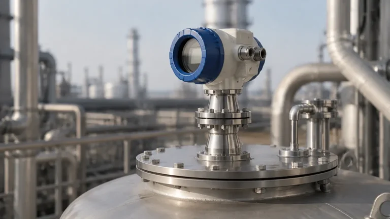
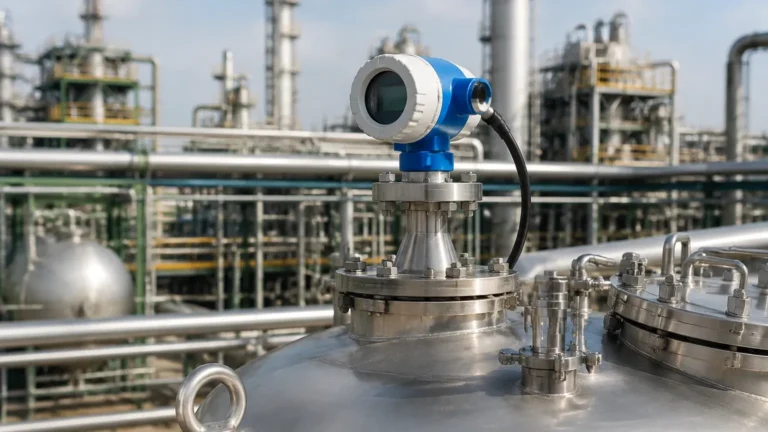
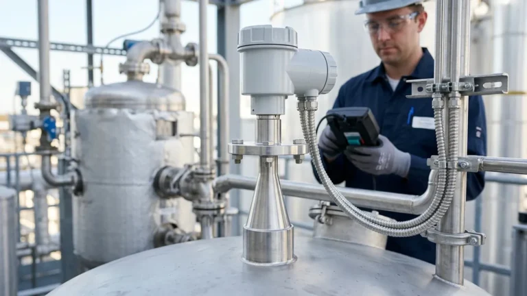
Contact Type Radar Level Transmitter
Contact Type Radar Level Transmitter: A Technical Engineering Guide to Guided Wave Radar
In the landscape of industrial process automation, achieving precise and repeatable level measurement is fundamental to operational safety and efficiency. While non-contact technologies are often the first choice for simple applications, complex process conditions—such as heavy foam, high-pressure steam, or low-dielectric media—frequently necessitate a more robust approach. The contact type radar level transmitter, technically known as Guided Wave Radar (GWR), has emerged as a primary solution for these challenging environments.
This article provides a comprehensive technical overview of contact type radar technology, exploring its operating principles, probe configurations, selection criteria, and the critical installation parameters that international procurement engineers must consider. For those evaluating high-performance instrumentation, understanding the mechanics of Radar Level Meters is the first step toward optimizing plant performance.
1. Measurement Principle: Time Domain Reflectometry (TDR)
Unlike traditional through-air radar that broadcasts electromagnetic waves through a horn or rod antenna, a contact type radar level transmitter utilizes a physical waveguide—a cable or rod—to direct the signal. The underlying technology is based on Time Domain Reflectometry (TDR).
The Signal Path
The transmitter electronics generate low-power microwave pulses (typically in the GHz range). These pulses are coupled onto a probe that extends into the process medium. The pulse travels along the probe at the speed of light. When the pulse encounters a change in the dielectric constant ($ε_r$) of the surrounding environment—specifically the transition from air or gas to the process liquid or solid—a portion of the pulse energy is reflected back toward the transmitter.
Calculation of Level
The instrument measures the time-of-flight (ToF) between the emission of the pulse and the reception of the reflected signal. Because the speed of the pulse along the waveguide is constant, the distance to the product surface is calculated using the formula:
Distance = (Speed of Light × Time of Flight) / 2
The transmitter then subtracts this distance from the total tank height (the reference point) to determine the actual level of the medium.
Why Contact Matters
The primary advantage of guiding the pulse along a probe is signal integrity. In non-contact systems, the radar beam spreads as it travels, losing energy and potentially reflecting off tank walls or internal obstructions (ladders, agitators). In a contact type radar level transmitter, the energy is concentrated in a tight cylinder around the probe, resulting in a significantly higher signal-to-noise ratio. This makes GWR exceptionally effective in measuring media with low dielectric constants or in tanks with turbulent surfaces.
2. Probe Configurations and Their Applications
Selecting the correct probe geometry is the most critical decision in the specification of a contact type radar level transmitter. Probes are generally categorized into three types: single-pole, double-pole, and coaxial.
2.1 Single Cable or Rod Probes
Single-pole probes consist of a single stainless steel rod or flexible cable. These are the most common due to their versatility and ease of cleaning.
* Best For: Liquids with high dielectric constants, viscous fluids, and applications where coating or buildup is a concern.
* Constraint: They are more sensitive to electromagnetic interference and require a minimum distance (typically 300 mm or 12 inches) from tank walls and internal metal structures to avoid false reflections.
2.2 Double Cable or Rod Probes
These consist of two parallel conductors. The microwave pulse travels between the two poles, creating a more concentrated electromagnetic field than the single-pole design.
* Best For: Media with lower dielectric constants ($ε_r$ > 1.9) and longer measurement ranges in large silos.
* Constraint: They are prone to bridging; if viscous material or solids get stuck between the two conductors, the instrument will report a false high level.
2.3 Coaxial Probes
The coaxial probe functions like a high-frequency cable, with a central rod housed inside an outer perforated tube. The electromagnetic field is entirely contained within the tube.
* Best For: Low dielectric liquids ($ε_r$ as low as 1.4), highly turbulent surfaces, and tanks with many internal obstructions. Since the field is contained, the probe can be installed very close to walls or pipes.
* Constraint: Limited to clean, low-viscosity liquids. Any solids or sticky substances that enter the tube can cause blockages and measurement failure.
3. Key Selection Criteria for Industrial Applications
When specifying a contact type radar level transmitter for a project, engineers must align the instrument's capabilities with the physical properties of the process.
3.1 Dielectric Constant (ε_r)
The dielectric constant of the medium determines how much energy is reflected. Water has a high ε_r (~80), providing a strong reflection. Hydrocarbons like oil or diesel have low ε_r (~2.0), requiring more sensitive electronics and often a coaxial or double-probe design. If the dielectric constant is below 1.4, standard GWR may struggle to detect the surface.
3.2 Temperature and Pressure
Industrial processes often involve extreme conditions. Standard GWR units typically handle up to 150°C (302°F) and 4 MPa (580 psi). However, high-temperature/high-pressure versions from manufacturers like Welk can extend these limits to 400°C (752°F) and 40 MPa (5800 psi) by using specialized ceramic seals and cooling fins to protect the electronics.
3.3 Interface Measurement
One of the unique capabilities of contact type radar is the ability to measure both the total level and the interface level between two liquids (e.g., oil over water). This is possible if the upper liquid has a lower dielectric constant than the lower liquid. The pulse partially reflects off the top surface and continues through the upper liquid to reflect off the interface.
4. Installation Guidelines and Constraints
Proper installation is paramount to the accuracy of a contact type radar level transmitter. Even the most advanced sensor will fail if the physical environment interferes with the waveguide.
4.1 Nozzle Considerations
The nozzle (the mounting point on top of the tank) must be sized correctly. For rod or cable probes, the nozzle diameter should be as large as possible to minimize "ringing" near the top of the probe. If the nozzle is very tall and narrow, it can create a large "dead zone" or blocking distance at the top of the tank where measurement is impossible.
4.2 Proximity to Tank Walls
For single-probe designs, maintaining a clearance from the tank wall is essential. A general rule of thumb is a minimum of 300 mm (approx. 12 inches). If the tank is made of plastic or fiberglass, the probe requires a metal launching plate or flange to provide a proper ground reference for the signal.
4.3 Avoiding Obstructions
The probe should not touch any internal tank structures. In the case of flexible cable probes used in tall silos, engineers must account for the "swing" of the cable during filling or agitation. If the probe touches a metal wall or ladder, it will create a short circuit for the microwave pulse, resulting in a false level reading at that point.
4.4 Pull-Down Forces in Solids
When using a contact type radar level transmitter in solid materials (like grain, cement, or plastic pellets), the medium exerts a significant downward force on the cable probe during discharge. This is known as the pull-down force. Engineers must ensure the tank roof and the probe's process connection are rated to withstand several tons of force, depending on the silo height and material density.
5. Comparison Table: Contact vs. Non-Contact Radar
| Feature | Contact Radar (GWR) | Non-Contact Radar (Pulse/FMCW) |
| :— | :— | :— |
| Measurement Path | Along a physical probe | Through the air/vapor space |
| Foam Resistance | Excellent (penetrates foam) | Moderate to Poor (foam absorbs signal) |
| Dust/Steam Impact | Negligible | Can attenuate the signal |
| Turbulence | High resistance | May cause signal loss |
| Installation | Requires probe to reach bottom | Top-mounted, no contact |
| Minimum ε_r | Can measure down to 1.4 | Usually requires > 1.9 |
| Maintenance | Probe may require cleaning | Low maintenance (no contact) |
6. Limitations and Application Risks
While highly reliable, the contact type radar level transmitter is not a universal solution. Engineers should be aware of the following risks:
* Material Build-up: In extremely sticky media, material can bridge between the probe and the tank nozzle, or coat the probe so thickly that the signal is attenuated. While GWR is better at handling coating than ultrasonic sensors, excessive buildup will eventually degrade accuracy.
* Corrosion: Because the probe is in constant contact with the medium, material selection (316L Stainless Steel, Hastelloy, PTFE coating) is critical. Corrosive failure of the probe can lead to process leaks.
* Mechanical Stress: As mentioned, in bulk solids, the mechanical load on the cable can lead to probe breakage or tank roof deformation if not properly engineered.
* Dead Zones: All GWR sensors have an "Upper Blocking Distance" (typically 100 mm to 500 mm depending on the probe and nozzle) and a "Lower Dead Zone." Measurement in these areas is either impossible or significantly less accurate.
7. Frequently Asked Questions (FAQ)
Q: Can a contact type radar level transmitter measure the level of solids?
A: Yes, GWR is very effective for solids. Cable probes are typically used for tall silos. However, the dielectric constant of the solid must be considered, and the mechanical pull-down forces must be calculated.
Q: How does the probe length affect accuracy?
A: Probe length does not inherently affect accuracy, but it does define the measurement range. Probes can be manufactured in lengths from 300 mm to over 30 meters (approx. 1 foot to 100 feet). For very long ranges, flexible cables are used instead of rigid rods.
Q: Does the probe need to be anchored to the bottom of the tank?
A: In tanks with high agitation or flow, a cable probe should be anchored to prevent it from hitting the tank walls or agitator blades. However, if the probe is anchored, a tensioning spring or weight must be used to allow for thermal expansion and contraction.
Q: Can I cut the probe to length on-site?
A: Many rod and cable probes are designed to be field-cuttable. After cutting, the transmitter's configuration software must be updated with the new probe length to maintain accuracy.
8. Conclusion
The contact type radar level transmitter remains a cornerstone of industrial level instrumentation, particularly where non-contact methods fail due to environmental interference. By guiding the microwave signal directly to the surface, GWR provides a level of reliability that is essential for critical process control and safety-instrumented systems (SIS).
When selecting a device, it is imperative to provide the manufacturer with detailed process data, including the dielectric constant, temperature range, and potential for probe coating. For further technical specifications and to explore various probe options, engineers are encouraged to Review product options and application support to ensure the selected instrument meets the specific demands of their industrial environment.