Capacitive Level Sensors
Capacitive Level Sensors
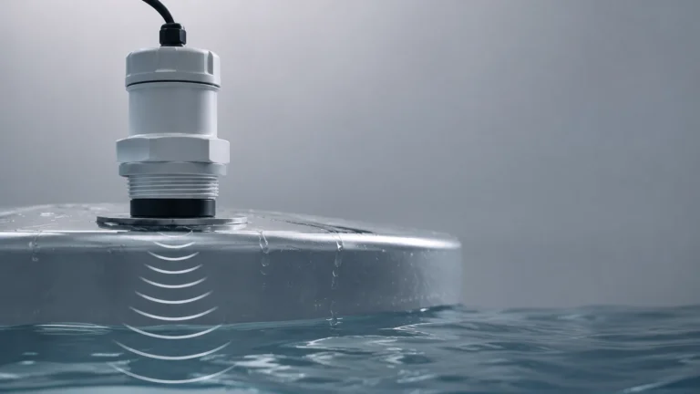
In the landscape of industrial process control, capacitive level sensors represent one of the most versatile and robust technologies for monitoring the presence or volume of materials within a vessel. As a professional manufacturer, Welk provides these instruments to address complex measurement challenges in water treatment, chemical processing, and oil and gas industries. This guide serves as a practical engineering reference for understanding, selecting, and installing capacitive level measurement systems.
Understanding the Measurement Principle
The operation of capacitive level sensors is based on the electrical principle of capacitance. A capacitor consists of two conductive plates separated by an insulating material known as a dielectric. The ability of this system to store an electrical charge is defined as capacitance ($C$), which is determined by the formula:
$$C = \epsilon_0 \cdot \epsilon_r \cdot \frac{A}{d}$$
Where:
* $\epsilon_0$ is the permittivity of free space.
* $\epsilon_r$ is the relative permittivity (dielectric constant) of the material between the plates.
* $A$ is the surface area of the plates.
* $d$ is the distance between the plates.
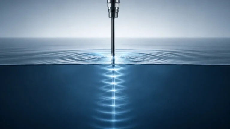
In an industrial tank application, the sensor probe (electrode) and the tank wall (the second electrode) form the two plates of a capacitor. If the tank is non-conductive, a ground reference rod or a second probe is used. As the level of the process material rises, it displaces the air or gas (which has a dielectric constant of approximately 1) with a material that has a different dielectric constant. This change in the total dielectric property of the medium between the electrodes causes a proportional change in capacitance, which the electronics convert into a level signal.
Conductive vs. Non-Conductive Media
The measurement approach differs significantly depending on the electrical conductivity of the medium:
1. Non-Conductive Media (e.g., Oils, Hydrocarbons): The material acts as the dielectric. The probe is usually a bare metal rod. The change in capacitance is directly proportional to the height of the material covering the probe.
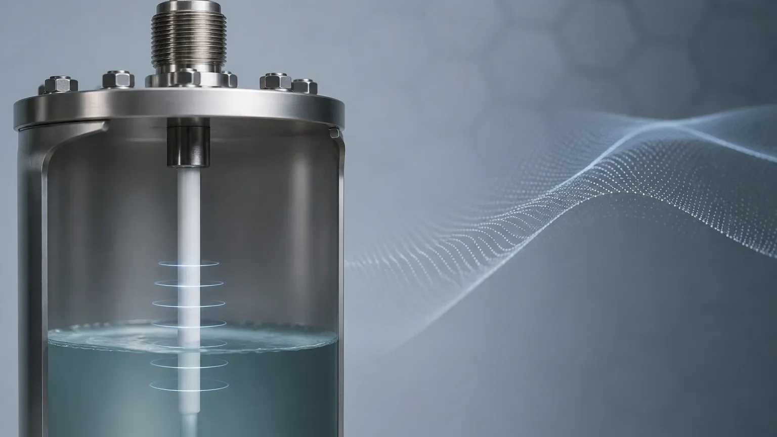
2. Conductive Media (e.g., Water-based liquids, Acids): The material acts as an extension of the tank wall (the ground electrode). To prevent a short circuit, the sensor probe must be covered with an insulating sheath (typically PTFE, PFA, or FEP). In this configuration, the insulation itself becomes the dielectric, and the capacitance changes as the conductive liquid covers more of the insulated probe's surface area.
Types of Capacitive Level Sensors
Capacitive technology is adaptable to various mechanical configurations depending on the depth of the vessel and the nature of the material.
Point Level Switches
These sensors are designed to detect the presence or absence of material at a specific height. They are commonly used for high-level alarm (overfill protection) or low-level alarm (pump dry-run protection). They are compact and often feature "active shield" technology to ignore material build-up on the probe.
Continuous Level Transmitters
For applications requiring real-time monitoring of the entire tank volume, continuous transmitters are used. These provide a 4-20mA, HART, or Modbus output proportional to the level. For more information on the full range of industrial instrumentation, you can visit the Main Page of the Welk product catalog.
Probe Configurations
* Rod Probes: Best suited for shorter distances (typically up to 3 meters or 10 feet). They are rigid and offer high stability in turbulent liquids.
* Cable Probes: Used for deep tanks or silos, reaching lengths up to 30 meters (approx. 100 feet). They utilize a weighted flexible cable to maintain vertical alignment.
Material Selection and Dielectric Constants
The success of a capacitive level sensor installation depends heavily on the dielectric constant ($\epsilon_r$) of the process material. Materials with higher dielectric constants are easier to measure because they produce a larger change in capacitance.
| Material | Dielectric Constant ($\epsilon_r$) | Measurement Difficulty |
| :— | :— | :— |
| Air / Vacuum | 1.0 | N/A (Reference) |
| Plastic Pellets | 1.1 – 2.0 | High (Requires high sensitivity) |
| Mineral Oil | 2.0 – 2.2 | Moderate |
| Grains/Cereals | 3.0 – 5.0 | Low |
| Ethanol | 24 – 25 | Very Low |
| Water | 80 – 81 | Very Low |
When the dielectric constant is below 2.0, standard capacitive sensors may struggle to distinguish between the material and air. In such cases, specialized high-sensitivity electronics or alternative technologies like guided wave radar may be required.
Practical Selection Table for Industrial Applications
Choosing the right sensor involves balancing chemical compatibility, physical constraints, and electrical properties.
| Application | Recommended Probe Type | Insulation Material | Key Consideration |
| :— | :— | :— | :— |
| Potable Water | Insulated Rod | PTFE / PFA | Ensure food-grade certifications. |
| Sulfuric Acid | Insulated Rod | PFA / Hastelloy | High chemical resistance required for both probe and seal. |
| Diesel Fuel | Bare Rod | None (Non-conductive) | Low dielectric constant; ensure stable grounding. |
| Cement Silos | Heavy-duty Cable | None / Partial | High tensile strength needed for pull-forces of solids. |
| Wastewater | Insulated Rod | PTFE | Build-up resistance is critical; use active shield probes. |
Installation Guidelines and Best Practices
Proper installation is critical to ensure the accuracy and longevity of capacitive level sensors. Engineers should adhere to the following technical requirements:
1. Grounding and Reference: Capacitance measurement requires a reference electrode. In metal tanks, the tank itself serves as the ground. In plastic or concrete tanks, a ground tube (concentric shield) or a secondary ground rod must be installed parallel to the sensing probe.
2. Mounting Position: The probe should be mounted away from the tank wall to prevent interference. A general rule is to maintain a minimum distance of 100 mm (approx. 4 inches) from the wall. Avoid installing the sensor directly in the path of the material inflow to prevent false readings and mechanical wear.
3. No-Measurement Zone (Dead Zone): There is typically a small area at the very top of the probe (near the process connection) where measurement is not possible. This is known as the "inactive length" or dead zone. Ensure the tank's maximum fill level does not exceed this zone.
4. Pressure and Temperature: Ensure the process connection (flange or thread) and the internal seals are rated for the maximum operating pressure (e.g., 4.0 MPa) and temperature (e.g., 200°C) of the vessel.
5. Cable Handling: For cable-type probes, ensure the weight at the bottom does not touch the floor of the tank, as this could lead to mechanical damage or electrical shorting if the cable is insulated.
Limitations and Operational Risks
While capacitive level sensors are highly versatile, certain conditions can impact their performance:
* Material Build-up: Conductive coatings or sticky residues on the probe can create a "virtual level," causing the sensor to report a high level even when the tank is empty. Welk solves this through "active shield" or "compensation" circuits that ignore the capacitance of the coating.
* Changing Dielectric Constants: If the process involves mixing different liquids with varying dielectric constants (e.g., an oil-water interface where the ratio changes), the sensor may require frequent recalibration unless a compensating reference probe is used.
* Moisture Content in Solids: In bulk solids like grain or sand, a change in moisture content significantly alters the dielectric constant, leading to measurement errors.
* Vapor and Condensation: High-pressure steam or heavy condensation on the probe head can affect the signal. Using a probe with a gas-tight seal and proper insulation helps mitigate this risk.
Maintenance and Troubleshooting
Capacitive sensors are generally low-maintenance because they have no moving parts. However, periodic checks are recommended:
* Calibration Verification: Check the zero point (empty tank) and span (full tank) annually, especially if the process material has changed.
* Insulation Integrity: For insulated probes used in conductive liquids, inspect the PTFE/PFA cladding for nicks or abrasions. Even a pinhole leak can cause the sensor to fail if the liquid contacts the internal metal rod.
* Connection Tightness: Ensure the electrical housing is tightly sealed to prevent moisture ingress, which is a leading cause of electronics failure in outdoor or wash-down environments.
Frequently Asked Questions (FAQs)
Q: Can capacitive level sensors be used for interface measurement?
A: Yes. They are frequently used to detect the interface between two immiscible liquids with different dielectric constants, such as oil and water. The sensor must be calibrated to the specific dielectric properties of both fluids.
Q: How does foam affect the measurement?
A: It depends on the foam's density and conductivity. Dry foam with low dielectric constant is often ignored by the sensor, while wet, conductive foam may be detected as a liquid level. High-frequency capacitive sensors are better at penetrating foam.
Q: Is it necessary to empty the tank for calibration?
A: While a two-point calibration (empty and full) is the most accurate, many modern Welk transmitters allow for "dry calibration" by entering the dielectric constant and tank dimensions into the software, though this may be slightly less precise.
Q: What is the maximum temperature these sensors can handle?
A: Standard models typically handle up to 80°C (176°F), but high-temperature versions with ceramic insulators and cooling fins can operate in environments exceeding 200°C (392°F).
Conclusion
Capacitive level sensors offer a reliable, cost-effective solution for a wide range of industrial level sensing needs. By understanding the dielectric properties of the media and following strict installation protocols regarding grounding and probe placement, engineers can achieve high precision in both point and continuous level monitoring. For specific technical datasheets or to consult on a custom OEM project, reviewing available Main Page resources is the recommended next step for procurement and engineering teams.