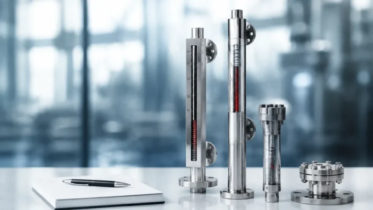
6 Inch Gauge
6 Inch Gauge
In the landscape of industrial process control, local level indication serves as a critical layer of safety and operational redundancy. While automated systems provide real-time data to control rooms, the physical presence of a reliable local indicator allows operators to verify tank levels on-site without relying solely on electronic signals. Among the various configurations used in heavy industry, the 6 inch gauge—specifically referring to the dial diameter of a secondary pressure-level transmitter or the visual scale width of a magnetic indicator—represents a standard for high-visibility monitoring in complex environments.
For engineers and plant managers, selecting the correct Magnetic & Local Level Gauges involves understanding the mechanical principles of buoyancy, magnetic coupling, and the specific environmental factors that dictate instrument longevity. This guide explores the technical foundations of these instruments, the significance of the 6-inch specification, and the practical considerations for integration into industrial automation workflows.
Measurement Principles of Magnetic & Local Level Gauges
Before selecting a specific gauge size or configuration, it is essential to understand how these instruments operate. Magnetic level gauges (MLGs) are based on two fundamental physical principles: buoyancy and magnetism.
The Buoyancy Principle
The core of the gauge is a float, which is engineered to have a density lower than the liquid being measured. As the liquid level in a vessel rises or falls, the float moves proportionally within a bypass chamber (or standpipe) that is connected to the vessel via side-side, top-bottom, or other nozzle configurations. This ensures that the liquid level in the chamber is identical to the level inside the main tank.
Magnetic Coupling and Indication
Inside the float is a high-intensity permanent magnet assembly. Outside the chamber, a visual indicator—often consisting of a series of bi-color magnetic flaps or a magnetic follower—is mounted. As the float moves, its internal magnetic field penetrates the non-magnetic chamber wall (typically stainless steel or alloy) and rotates the flaps or moves the follower.
This "coupling" ensures that the liquid remains entirely contained within the pressure-sealed chamber, eliminating the risk of leaks associated with traditional glass sight gauges. The 6 inch gauge specification often applies to the secondary dial indicators or the width of the display housing, ensuring that the level can be read clearly from a distance of several meters.
The Role of a 6 Inch Gauge in Level Monitoring
In the context of local level measurement, a "6 inch gauge" typically refers to the diameter of the dial face on a pressure-based level transmitter or a mechanical gauge used in conjunction with a magnetic level indicator. A 150 mm (6 inch) dial is a standard size for industrial applications where readability is paramount.
Visibility and Safety
In large-scale chemical plants or refineries, tanks can be several stories high. An operator standing at ground level may need to verify the status of a vessel located on a mezzanine. A 6-inch dial provides sufficient surface area for large numerals and clear graduations, reducing the likelihood of parallax error or misinterpretation during manual inspections.
Integration with Magnetic Level Gauges
While the primary indication on a magnetic level gauge is the vertical scale of flipping flags, many systems incorporate a secondary 6-inch dial gauge at the base or on a branch connection. This gauge may measure the hydrostatic pressure at the bottom of the column, providing a secondary verification of the liquid height based on the fluid's specific gravity.
Technical Specifications and Selection Criteria
Choosing the right instrument requires a detailed analysis of the process media and the physical environment. The following table outlines the primary evaluation criteria for Magnetic & Local Level Gauges in industrial settings.
| Parameter | Specification Detail | Importance |
| :— | :— | :— |
| Chamber Material | 316L Stainless Steel, Titanium, Hastelloy, or Plastics (PVC/PP) | Determines chemical compatibility and pressure rating. |
| Pressure Rating | From vacuum up to 200 bar (2900 psi) | Must exceed the maximum design pressure of the vessel. |
| Temperature Range | -196°C to +450°C (-320°F to 842°F) | Affects magnet stability and material expansion. |
| Fluid Density | Minimum 0.4 g/cm³ | The float must be specifically weighted to the fluid's specific gravity. |
| Dial Size | 100 mm (4 inch) or 150 mm (6 inch) | Dictates the distance from which the gauge can be accurately read. |
| Connection Size | DN15 to DN100 (1/2" to 4") | Must match existing vessel nozzles or flanges. |
Material Compatibility
For corrosive applications, such as those found in water treatment or chemical processing, Welk provides gauges constructed from specialized alloys or fluoropolymer-lined stainless steel. If the application involves high-purity water, the internal surfaces must be polished to prevent bacterial growth or contamination.
Installation Considerations for Magnetic Level Gauges
Proper installation is vital for the accuracy and safety of a 6 inch gauge system. Because these instruments rely on mechanical movement and magnetic fields, several factors must be addressed during the engineering phase.
1. Vertical Alignment: The bypass chamber must be installed perfectly vertical. Any significant tilt can cause the float to rub against the chamber walls, leading to friction that prevents the float from tracking the liquid level accurately.
2. Magnetic Interference: Since the gauge operates on magnetic coupling, it must be kept away from large ferrous structures or high-voltage cables that could generate electromagnetic fields. These can distort the magnetic field of the float and lead to false readings.
3. Isolation Valves: It is standard practice to install isolation valves between the vessel and the gauge chamber. This allows the gauge to be serviced, cleaned, or replaced without depressurizing the entire process vessel.
4. Venting and Draining: Every MLG installation should include a vent valve at the top and a drain valve at the bottom. This facilitates the removal of trapped air during startup and the flushing of sediment that may accumulate in the bottom of the chamber.

Limitations and Application Boundaries
While Magnetic & Local Level Gauges are highly versatile, they are not suitable for every application. Understanding these boundaries prevents instrument failure and safety hazards.
* High Viscosity and Coating: Fluids that are extremely viscous or tend to crystallize can impede the movement of the internal float. In such cases, the float may become stuck, providing a static (and incorrect) level reading.
* Ferrous Contaminants: If the process fluid contains iron filings or magnetic particles, these will adhere to the float's internal magnet. Over time, this buildup increases the float's weight (causing it to sink) and can eventually jam the float inside the chamber.
* Extreme Turbulence: In vessels with high-speed agitators or heavy splashing, the float may bounce violently, leading to mechanical wear or damage to the magnetic flaps. Stilling wells or external bypass chambers are required to dampen these effects.
* Specific Gravity Fluctuations: Because the float is designed for a specific density, significant changes in the fluid composition or temperature (which changes density) will affect the accuracy of the level indication.
Maintenance and Troubleshooting for Reliable Performance
A 6 inch gauge is generally low-maintenance due to its seal-less design, but periodic inspections are necessary to ensure long-term reliability.
Cleaning the Chamber
In applications involving wastewater or crude oil, paraffin or sludge can build up inside the chamber. Operators should periodically use the drain valve to flush the chamber. If the buildup is significant, the float must be removed, and the chamber should be cleaned with a compatible solvent.
Testing the Indicator
To verify that the visual indicator is functioning, a handheld magnet can be passed along the outside of the scale. The flaps should flip smoothly and remain in position. If flaps fail to rotate or appear stuck, the indicator rail may be misaligned or damaged.
Float Integrity
If the level indicator consistently reads "empty" despite the vessel being full, the float may have lost its buoyancy (collapsed due to over-pressure) or the internal magnet may have demagnetized due to exposure to temperatures exceeding its Curie point. In these instances, the float must be replaced with a unit matching the original specifications.
Frequently Asked Questions (FAQ)
Q: Can a 6 inch gauge be used for interface level measurement?
A: Yes. By adjusting the weight of the float, a magnetic level gauge can be designed to sink through a top layer of low-density liquid (e.g., oil) and float on a bottom layer of higher-density liquid (e.g., water). This allows for the local indication of the interface level.
Q: What is the benefit of a 6-inch dial over a 4-inch dial?
A: The primary benefit is readability. A 6-inch (150 mm) dial has roughly 2.25 times the surface area of a 4-inch (100 mm) dial, allowing for more granular scale divisions and better visibility in low-light or long-distance scenarios.
Q: Are these gauges suitable for high-pressure steam applications?
A: Yes, provided the chamber and float are engineered for the specific pressure and temperature ratings of the steam. Magnetic gauges are often preferred over glass gauges in steam service because they eliminate the risk of glass erosion and catastrophic breakage.
Q: How do I choose between a top-mounted and a side-mounted gauge?
A: Side-mounted gauges are standard for most tanks as they allow for easy access and maintenance. Top-mounted gauges are used when side nozzles are not available or for underground storage tanks where only the top of the vessel is accessible.
By adhering to these technical guidelines and selecting high-quality Magnetic & Local Level Gauges, industrial facilities can ensure precise, safe, and durable level monitoring. Whether utilizing a 6 inch gauge for its superior visibility or integrating complex magnetic floats for hazardous chemicals, the fundamental goal remains the same: providing clear, mechanical certainty in an increasingly digital world.