9 Gauges
9 Gauges
In industrial process control, local level indication serves as a critical safety and operational layer. While digital transmitters provide data to centralized control rooms, the physical presence of Magnetic & Local Level Gauges offers onsite operators a reliable, power-independent method to verify tank levels. Whether a project requires a single unit or a complex array of 9 gauges for a multi-stage distillation column, understanding the underlying physics and selection criteria is essential for long-term reliability.
This guide examines the engineering principles, selection parameters, and installation requirements for local level gauges, providing a technical framework for engineers and procurement specialists.
Measurement Principles of Magnetic Level Gauges
The most common form of local level indication in modern B2B applications is the magnetic level gauge (MLG). These instruments operate on two fundamental physical principles: buoyancy and magnetism.
The Buoyancy Principle
An MLG consists of a bypass chamber (a vertical pipe) connected to the side of a vessel. According to Archimedes' principle, the liquid level in the chamber will equalize with the level in the vessel. Inside this chamber is a float specifically engineered to match the density of the process fluid. The float rises and falls with the liquid level.
Magnetic Coupling
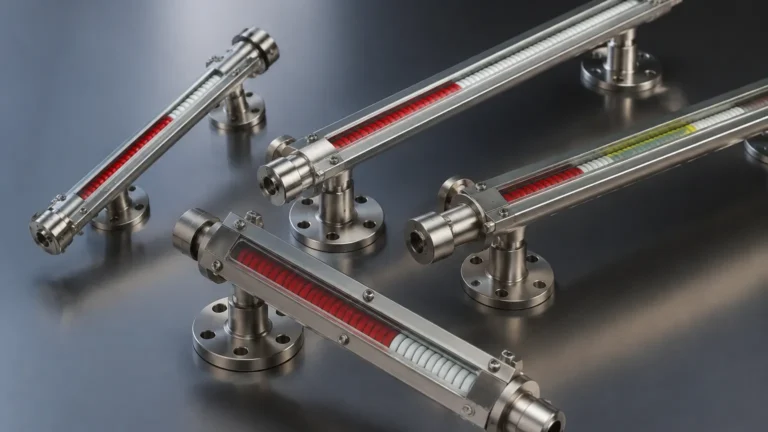
Inside the float is a permanent magnet assembly. Outside the chamber, an indication rail is mounted. This rail contains a series of bi-color (usually red and white) magnetic flaps or a magnetic follower. As the float moves, the magnetic field passes through the non-magnetic chamber wall (typically stainless steel) and flips the flaps or moves the follower. This provides a clear, high-visibility representation of the liquid level without the process fluid ever coming into contact with the indicator glass or flaps.
9 Critical Selection Criteria for Local Level Gauges
When specifying a suite of instruments—for instance, when a project requires the installation of 9 gauges across different chemical storage units—the following technical factors must be evaluated to ensure compatibility and safety.
1. Process Fluid Density (Specific Gravity): The float must be precisely weighted to float in the specific liquid. If the density is too low, a standard float may sink; if too high, it may not submerge enough to align the magnets correctly.
2. Design Pressure: Chambers must be rated for the maximum possible pressure of the vessel. For high-pressure applications, thicker walls are required, which in turn necessitates more powerful magnetic circuits to penetrate the steel.
3. Operating Temperature: Extreme temperatures affect both the magnetism of the float and the structural integrity of the chamber. High-temperature gauges often require insulation jackets or special magnetic alloys.
4. Material Compatibility: The chamber and float materials must be resistant to the process medium. Common materials include 316L Stainless Steel, Titanium, Hastelloy, and plastics like PVC or PVDF for corrosive acids.
5. Center-to-Center Distance: This is the measurement between the process connections. In a system involving 9 gauges, ensuring uniform center-to-center distances can simplify piping and maintenance spares.
6. Connection Type: Options include flanged, NPT threaded, or socket weld connections. The choice depends on the existing vessel nozzles and the required pressure rating.
7. Visibility Requirements: For large-scale facilities, indicators must be visible from a distance. Wide-flag indicators or illuminated rails are often specified for outdoor or low-light environments.
8. Redundancy and Switching: Many local gauges are equipped with magnetic switches or reed-chain transmitters to provide point-level alarms or 4-20mA signals to a PLC.
9. Environmental Conditions: Consideration for ambient temperature, UV exposure, and salt spray (in offshore applications) determines the housing material for the indicator rail.
Technical Selection Table
The following table provides a general reference for selecting the appropriate gauge configuration based on common industrial applications.
| Application Type | Typical Material | Pressure Range (bar) | Temperature Range (°C) | Indicator Type |
| :— | :— | :— | :— | :— |
| Water Treatment | 304/316 Stainless | Up to 40 | -20 to 150 | Bi-color Flaps |
| Chemical Storage | PVC / PP / PVDF | Up to 6 | -10 to 80 | Magnetic Follower |
| Oil & Gas (High P) | 316L / Alloy 20 | Up to 200+ | -50 to 400 | High-Visibility Flaps |
| Cryogenic Fluids | 316L (Vacuum Jacketed) | Up to 25 | -196 to 50 | Frost-Protected Scale |
| Boiler Steam | Carbon Steel / 316 | Up to 100 | Up to 350 | Magnetic Flaps |
Installation and Commissioning Best Practices
Proper installation is paramount to the accuracy of Magnetic & Local Level Gauges. Even if an engineer has successfully installed 9 gauges in the past, each new application requires a review of the following steps:
Vertical Alignment
The bypass chamber must be installed perfectly vertical. Any significant tilt will cause the float to rub against the chamber walls, leading to friction that can cause the float to "stick" or jump, resulting in inaccurate readings.
Magnetic Interference
Because the system relies on magnetic coupling, the gauge must be kept away from large ferrous structures or high-voltage electrical lines that could create electromagnetic interference. If multiple gauges are installed close together (e.g., a cluster of 9 gauges on a manifold), ensure there is sufficient spacing to prevent magnetic cross-talk between floats.
Venting and Draining
Every installation should include a vent valve at the top and a drain valve at the bottom. This allows for safe commissioning, as the air must be bled from the chamber for the liquid to enter, and the chamber must be drained for maintenance.
Initial Filling
When first introducing the process fluid, valves should be opened slowly. A sudden surge of liquid can slam the float into the top of the chamber, potentially damaging the internal magnet or the float itself.

Operational Limitations and Considerations
While highly reliable, local level gauges have specific limitations that must be managed:
* Viscosity: Extremely viscous liquids (above 500 cP) can impede float movement. In such cases, larger diameter chambers or heated tracing may be required.
* Particulates: Ferrous particles in the process fluid can accumulate on the float's magnet, eventually weighing it down or causing it to jam. Magnetic filters (traps) should be installed in the bypass line if solids are present.
* Coating: Liquids that tend to crystallize or leave heavy deposits can coat the float and the interior of the chamber, changing the buoyancy and requiring frequent cleaning.
* Flashing: If the liquid in the chamber boils or "flashes" due to a pressure drop, the resulting gas bubbles can cause the float to bounce violently, leading to unstable readings.
Maintenance and Troubleshooting
For a plant manager overseeing a fleet of instruments, such as a set of 9 gauges, a standardized maintenance schedule is recommended.
1. Visual Inspection: Regularly check the indicator rail for damaged flaps or moisture ingress behind the glass.
2. Float Integrity: Periodically remove the float to check for signs of corrosion, pitting, or liquid ingress (which would indicate a leak in the float).
3. Flushing: Use the drain and vent valves to flush the chamber and remove any accumulated sediment.
If the indicator stops following the level, first check for magnetic debris in the chamber. If the flaps are "stuck" in one color, a handheld magnet can often be used to reset them, though this usually indicates the float has passed too quickly or there is a mechanical obstruction.
Frequently Asked Questions (FAQs)
Q: Can magnetic level gauges be used for interface measurement?
A: Yes. By weighting the float to a density between the two liquids (e.g., oil and water), the float will sink through the upper layer and float on the lower layer, indicating the interface level.
Q: What happens if the float is installed upside down?
A: The magnet assembly inside the float is usually offset to account for the float's center of gravity. If installed upside down, the magnet will not align with the indicator rail, and the gauge will fail to provide a reading.
Q: Are these gauges suitable for high-vibration environments?
A: Standard magnetic flaps can sometimes be affected by extreme vibration. In these cases, a magnetic follower (a single moving piece) or dampened flaps are preferred.
Q: How do I choose between a glass sight gauge and a magnetic level gauge?
A: Glass sight gauges allow direct viewing of the fluid but are prone to breaking and leaking. Magnetic gauges are much safer for high-pressure, toxic, or flammable fluids because the process liquid is entirely contained within a metal chamber.
Q: Can I add a transmitter to an existing gauge later?
A: Yes, most high-quality Magnetic & Local Level Gauges allow for the external mounting of reed-chain or magnetostrictive transmitters without breaking the process seal, making them easily upgradeable for automation projects involving 9 gauges or more.