Automated Sampling
Automated Sampling
In modern industrial processing, the ability to obtain precise, representative data from liquid streams is fundamental to quality control, environmental compliance, and process optimization. Automated sampling refers to the programmed extraction of a physical sample from a process line or storage tank without manual intervention. This process is rarely a standalone operation; it relies heavily on integrated instrumentation to determine "when" and "how much" to sample.
For engineers and plant managers, the synergy between automated sampling units and level measurement instruments is critical. Whether managing a wastewater treatment facility or a chemical refinery, the accuracy of a sample is often dictated by the precision of the level or flow data provided by sensors. As a professional manufacturer, Welk provides the foundational level measurement technologies—including radar, ultrasonic, and hydrostatic sensors—that serve as the primary triggers for these sophisticated sampling systems. To explore the full range of instrumentation supporting these applications, you may visit our Main Page.
Principles of Automated Sampling and Level Integration
Automated sampling is governed by the need for a "representative sample." A sample is only useful if its chemical and physical properties mirror the bulk material at the time of extraction. To achieve this, sampling systems typically operate based on three primary principles, all of which require reliable level or flow monitoring.
Time-Proportional Sampling
Samples are taken at fixed time intervals (e.g., every 15 minutes). While simple, this method ignores changes in process volume. Level sensors are used here primarily as a safety interlock, ensuring the sampler does not attempt to draw from an empty pipe or tank, which could damage the pump.
Flow-Proportional Sampling
This is the most common method in industrial discharge monitoring. The system takes samples based on the volume of liquid passing a point. Since flow in open channels or partially filled pipes is calculated based on the liquid level (using flumes or weirs), high-precision ultrasonic or radar level meters are essential. The sensor measures the head level, converts it to a flow rate, and signals the automated sampling unit to trigger after a specific volume (e.g., every 1,000 liters) has passed.
Event-Based Sampling
Sampling is triggered by a specific process condition, such as a high-level alarm. For instance, in a storm overflow tank, a hydrostatic level transmitter might detect a sudden rise in water level, triggering the automated sampling system to capture the initial "first flush" of runoff for environmental analysis.
Level Measurement Technologies for Sampling Support
Selecting the right level instrument is the first step in designing an effective automated sampling protocol. The following technologies are the industry standards for providing the necessary data inputs.
Radar Level Meters
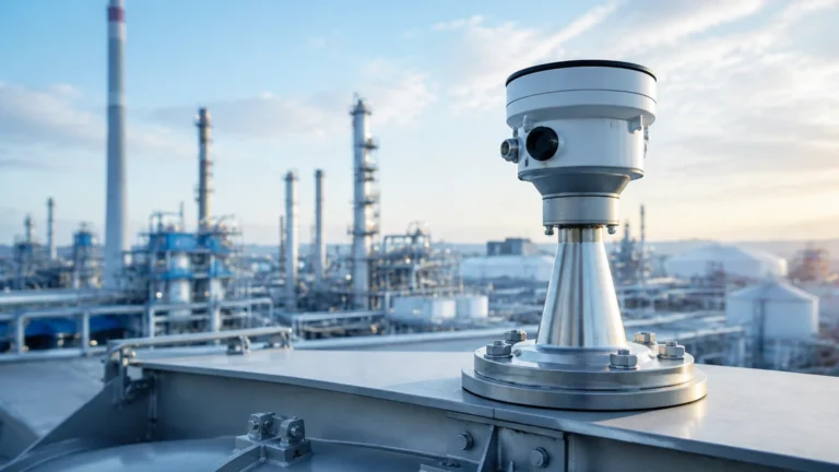
Radar level meters, particularly those operating in the 26GHz or 80GHz frequency range, offer non-contact measurement. They emit microwave pulses that reflect off the liquid surface. Because they do not touch the medium, they are ideal for sampling corrosive chemicals or liquids with high solids content. They remain accurate regardless of vapor, pressure, or temperature fluctuations.
Ultrasonic Level Sensors
Ultrasonic sensors use sound waves to determine the distance to the liquid surface. These are cost-effective solutions for water and wastewater applications. In automated sampling, they are frequently used in open-channel flow measurement to provide the "trigger" signal for flow-proportional samplers.
Hydrostatic Level Transmitters
These sensors measure the pressure exerted by the liquid column. They are submerged at the bottom of a tank or well. Hydrostatic transmitters are favored in deep wells or reservoirs where non-contact sensors might struggle with physical obstructions. They provide a continuous 4-20mA signal that can be integrated directly into the sampler's controller.
Technical Comparison for Sampling Applications
When specifying equipment for an automated sampling project, consider the following technical boundaries:
| Technology | Measurement Principle | Best Application | Limitations |
| :— | :— | :— | :— |
| Radar (Non-contact) | Microwave reflection | Chemical tanks, volatile liquids, high precision | Higher initial cost than ultrasonic |
| Ultrasonic | Sound wave TOF | Wastewater, open channels, sumps | Affected by heavy foam or high wind |
| Hydrostatic | Pressure sensing | Deep wells, pressurized vessels | Subject to wear in abrasive slurries |
| Magnetic Gauge | Buoyancy/Magnetic coupling | High-pressure boilers, oil/gas | Limited to clean liquids; mechanical parts |
Installation Considerations for Integrated Systems
For automated sampling to be successful, the level sensor and the sampling intake must be positioned correctly relative to one another. Poor installation leads to "slug" sampling or air intake, rendering the data useless.
1. Stilling Wells and Turbulence: If the sampling point is in a highly turbulent area (near an agitator or inlet pipe), level readings will fluctuate. Use a stilling well for radar or ultrasonic sensors to ensure a smooth surface for measurement. The sampling intake should be placed nearby but not so close that it interferes with the sensor’s signal path.
2. Dead Zones (Blocking Distance): All ultrasonic and radar sensors have a "dead zone" directly beneath the sensor where measurement is impossible. Ensure the maximum expected liquid level remains at least 0.2m to 0.5m (0.6ft to 1.6ft) below the sensor face.
3. Intake Positioning: The sampling tube should be positioned in the center of the flow stream, typically at a depth of 60% of the total liquid level, to avoid bottom sediments and surface oils. The level sensor provides the data to ensure the intake remains submerged at this optimal depth.
4. Signal Integration: Most automated sampling units accept a 4-20mA or Modbus signal. Ensure the level meter is calibrated so that 4mA represents the "Empty" state and 20mA represents the "Full" state, matching the scaling in the sampler’s software.

Limitations and Common Risks
While automated sampling increases efficiency, engineers must be aware of specific limitations:
* Chemical Compatibility: The materials of the level sensor (e.g., PTFE, PVDF, or Stainless Steel) must be compatible with the sampled medium. A failing sensor will lead to missed sampling cycles.
* Foam Interference: In many industrial processes, surface foam can absorb ultrasonic signals or create false echoes for radar. In these instances, a hydrostatic transmitter or a high-frequency (80GHz) radar is preferred to maintain the sampling trigger.
* Maintenance Lag: Automated systems are often "set and forget." However, if the level sensor becomes coated in grease or scale, the sampling timing will drift. Regular cleaning of the sensor face is mandatory for system integrity.
Frequently Asked Questions (FAQ)
Q: Can I use a level switch instead of a continuous level transmitter for sampling?
A: Yes, if you only require event-based sampling. A level switch can trigger a sampler when a tank reaches a specific height. However, for flow-proportional sampling, a continuous transmitter (Radar/Ultrasonic) is required to calculate volume.
Q: How does temperature affect the sampling trigger?
A: Temperature primarily affects ultrasonic sensors because the speed of sound changes with air density. If your sampling occurs in an environment with extreme temperature swings, ensure your ultrasonic sensor has integrated temperature compensation or switch to radar, which is unaffected by temperature.
Q: What is the maximum distance between the level sensor and the sampler?
A: Using a standard 4-20mA signal, the sensor can be located hundreds of meters away from the sampler controller, provided shielded cabling is used to prevent electromagnetic interference. For digital protocols like RS485/Modbus, distances can be even greater.
Q: Is it possible to sample based on the interface between two liquids?
A: Yes. Using a magnetic level gauge or a specialized radar sensor, you can detect the interface between oil and water, for example. This allows the automated sampling system to draw specifically from the oil layer or the water layer as needed.
Conclusion
Automated sampling is a cornerstone of modern process engineering, but its reliability is only as good as the instrumentation that drives it. By integrating high-quality radar, ultrasonic, or hydrostatic level meters, facilities can ensure that every sample taken is a true reflection of the process state. Choosing the correct technology requires a balance of chemical compatibility, accuracy requirements, and environmental conditions.
Welk continues to support global industries with robust level measurement solutions designed for seamless integration with automated systems. For technical specifications and product selection guidance, please refer to our Main Page to find the ideal instrument for your specific application.