Bin Level Sensor
Bin Level Sensor
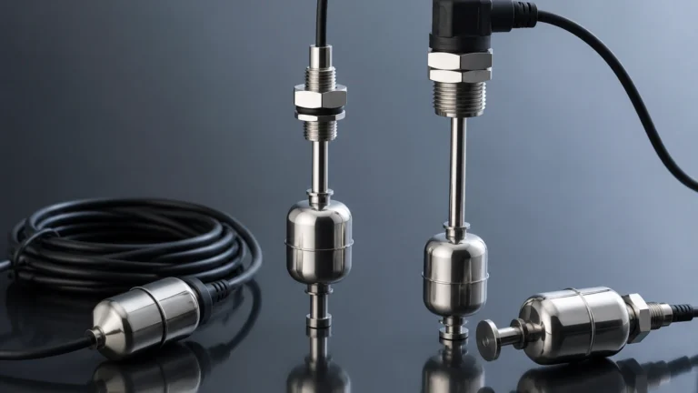
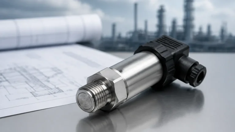
In industrial processing and storage, a bin level sensor is a critical component for inventory management, process automation, and overfill prevention. These devices are designed to detect the presence or quantify the volume of materials—ranging from fine powders and granular solids to viscous liquids—within silos, hoppers, and tanks. Selecting the appropriate sensor requires a deep understanding of the material properties, the vessel geometry, and the specific measurement physics involved.
Accurate level detection ensures that production lines remain fed, storage capacity is optimized, and hazardous spills or equipment damage caused by dry-running pumps are avoided. This guide examines the fundamental principles of bin level measurement, provides selection frameworks, and outlines best practices for installation and maintenance.
Understanding Bin Level Measurement Principles
Before selecting a bin level sensor, it is essential to understand the physical principles that govern different sensing technologies. These are generally categorized into mechanical, electrical, and acoustic or electromagnetic wave-based methods.
Mechanical Principles (Rotary and Diaphragm)
Rotary paddle sensors operate using a low-speed motor that rotates a paddle. When the material reaches the paddle, it provides mechanical resistance, stalling the motor and triggering a switch. Diaphragm or pressure switches rely on the physical weight of the material pressing against a sensitive plate to activate a microswitch.
Vibrating Principles (Tuning Forks and Rods)
These sensors use piezoelectric crystals to vibrate a sensing element at its resonant frequency. When the material covers the probe, the vibration is dampened. The electronic circuit detects this change in frequency or amplitude and converts it into a level signal. This method is highly effective for powders and granules.
Capacitance and Dielectric Principles
Capacitance sensors treat the sensor probe and the vessel wall as two plates of a capacitor. As the material (the dielectric) fills the space between them, the capacitance changes. This principle is sensitive to the dielectric constant of the material; materials with higher dielectric constants are generally easier to detect.
Time-of-Flight (Radar and Ultrasonic)
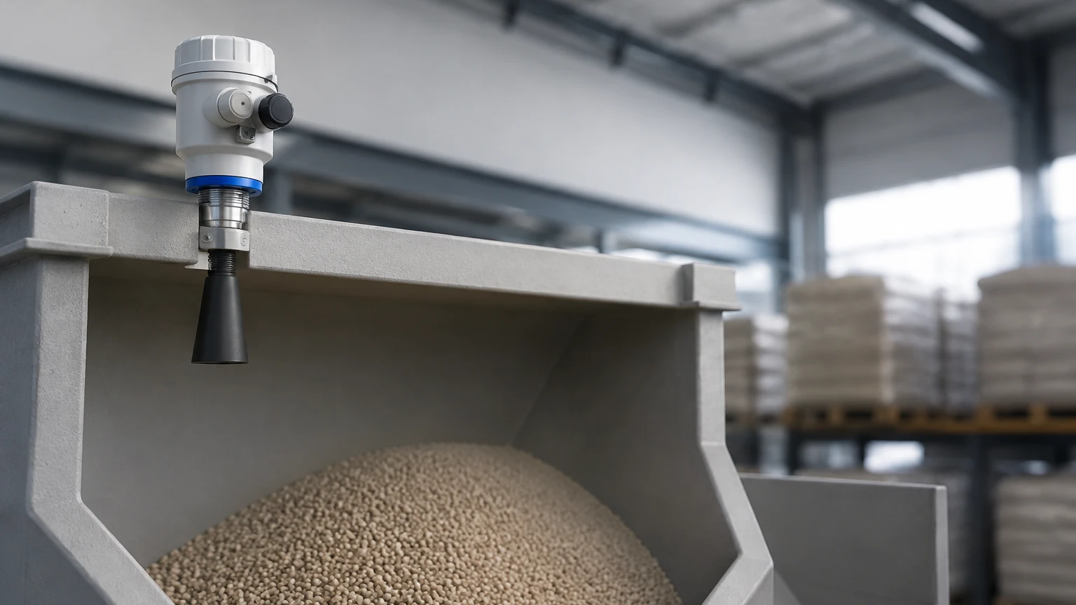
Continuous measurement often relies on Time-of-Flight (ToF). Ultrasonic sensors emit sound pulses that reflect off the material surface. Radar sensors (both guided and non-contact) emit electromagnetic microwave pulses. By measuring the time it takes for the pulse to return, the sensor calculates the distance to the material surface. Radar is typically preferred in dusty or high-temperature environments where sound waves may be attenuated or refracted.
Point Level vs. Continuous Level Monitoring
Bin level sensors are broadly divided into two functional types: point level and continuous level. The choice between them depends on whether the operator needs a simple "full/empty" alert or a real-time percentage of the bin's contents.
Point Level Sensors
Point level sensors are used to detect a specific level. They are commonly installed at the top of a bin for high-level alarms (to prevent overfilling) or at the bottom for low-level alarms (to prevent process interruptions).
- Pros: Lower cost, high reliability, simple integration.
- Cons: No information on the material level between the set points.
Continuous Level Sensors
Continuous level sensors provide a constant stream of data, typically via a 4-20mA signal, Modbus, or HART protocol. This allows for precise inventory tracking and trend analysis.
- Pros: Complete visibility of inventory, better process control.
- Cons: Higher initial investment, often requires more complex calibration.
For engineers looking to compare specific models and technical data sheets, the Main Page provides a detailed breakdown of both point and continuous measurement instruments.
Technical Selection Criteria for Bin Level Sensors
Choosing the wrong sensor can lead to frequent maintenance cycles or complete signal loss. The following factors must be evaluated during the specification phase:
1. Material Density and Particle Size: Low-density materials like fumed silica may not provide enough resistance for a rotary paddle, whereas heavy ores might damage delicate vibrating forks.
2. Dielectric Constant (εr): For radar and capacitance sensors, the material’s ability to reflect or store electrical energy is paramount. Non-conductive materials with low εr (like plastic pellets) require high-sensitivity radar units.
3. Angle of Repose: Unlike liquids, solids form a cone when loaded. The sensor must be positioned to account for the peak and valley of the material to avoid false readings.
4. Process Environment: High temperatures, vacuum or high-pressure conditions, and the presence of heavy dust or steam will dictate the housing material and the sensing technology (e.g., opting for radar over ultrasonic in dusty silos).
Practical Selection Table for Industrial Applications
The table below serves as a general guide for matching sensor technology to common industrial materials.
| Material Type | Recommended Technology | Measurement Type | Key Advantage |
| :— | :— | :— | :— |
| Fine Powders (Cement, Flour) | Vibrating Rod / Radar | Point / Continuous | Resists dust interference |
| Large Granules (Gravel, Coal) | Rotary Paddle / Radar | Point / Continuous | Robust mechanical design |
| Viscous Liquids (Resins, Oils) | Ultrasonic / Guided Wave Radar | Continuous | Non-contact or self-cleaning |
| Corrosive Chemicals | PTFE-coated Capacitance | Point | Chemical resistance |
| Lightweight Pellets | High-Sensitivity Capacitance | Point | Detects low-density solids |
Installation Guidelines and Best Practices
Correct installation is as important as sensor selection. Even the most advanced bin level sensor will fail if placed in a location where it is subjected to direct material flow or structural interference.
Avoid the Fill Stream
Never install a sensor directly under the inlet. The falling material will cause false high-level triggers and may mechanically damage the probe. If the inlet cannot be moved, a protective baffle or shield should be installed above the sensor.
Mounting Position and Nozzle Length
For radar and ultrasonic sensors, the "beam angle" must be considered. If the sensor is mounted too close to the wall, the signal may reflect off the wall or internal ladders rather than the material. Ensure the mounting nozzle is as short as possible to prevent signal interference within the neck of the nozzle.
Grounding and Static Electricity
In many dry bulk applications, the movement of material generates significant static electricity. Ensure the sensor and the bin are properly grounded to prevent electrostatic discharge (ESD) from damaging the sensor's electronics.
Metric and Imperial Considerations
Standard industrial installations typically use metric threads (e.g., M20x1.5) or NPT/BSP standards. Ensure that the mounting flange or thread matches the vessel's port. Typical detection ranges for large silos can extend up to 30 meters (approx. 98 feet) for radar, while point level probes are usually 100mm to 300mm (4 to 12 inches) in length.
Common Limitations and Operational Risks
While modern sensors are robust, they are not infallible. Understanding their limitations prevents operational surprises.
* Material Bridging: In some bins, material can stick to the walls or the sensor itself (bridging). This can make a point level sensor "think" the bin is full when it is actually empty. Vibrating sensors with polished surfaces or "active shield" capacitance probes can mitigate this.
* Dust Attenuation: In extremely dusty environments, ultrasonic sensors may lose their signal because the sound waves are absorbed by the dust cloud. In these cases, 80GHz high-frequency radar is the industry standard due to its ability to penetrate dust.
* Foam and Turbulence: In liquid bins, surface foam can absorb ultrasonic signals. Guided wave radar, which uses a physical probe to guide the signal, is often a more reliable choice for turbulent or foaming liquids.
Frequently Asked Questions (FAQ)
Q: Can a single bin level sensor work for both solids and liquids?
A: Many technologies, such as radar and capacitance, are versatile enough for both. However, the calibration and mounting hardware often differ. It is best to specify the medium during procurement.
Q: How often do these sensors need calibration?
A: Mechanical sensors like rotary paddles rarely need calibration but require periodic seal inspections. Electronic sensors like radar are often "plug-and-play," though they should be verified annually against a manual tape measure or a known reference point.
Q: What is the impact of temperature on sensor accuracy?
A: Ultrasonic sensors are highly sensitive to temperature because the speed of sound changes with air density. Most high-quality ultrasonic sensors include integrated temperature compensation. Radar sensors are largely unaffected by temperature fluctuations in the vapor space.
Q: Is it possible to detect levels in a pressurized bin?
A: Yes, but the sensor must be rated for the specific pressure. Non-contact radar and guided wave radar are excellent for pressurized vessels because they can be sealed with high-pressure glass or ceramic process seals.
For further technical support or to request a customized OEM solution for specific industrial requirements, visiting the Main Page will provide access to engineering experts and comprehensive product documentation.