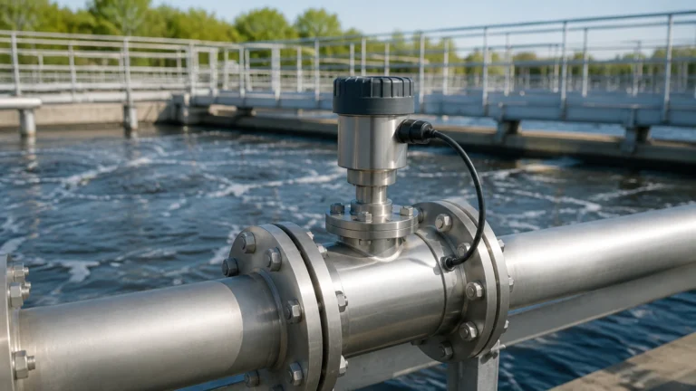
Capacitance Fuel Probe
Capacitance Fuel Probe
In the realm of industrial fluid management, the accurate measurement of fuel levels is critical for operational efficiency, safety, and cost control. Among the various technologies available, the capacitance fuel probe stands out as a robust and reliable solution for monitoring non-conductive liquids such as diesel, gasoline, and aviation fuels. This guide provides a comprehensive technical overview of capacitance-based measurement, selection criteria, and practical installation considerations for engineering professionals.
Measurement Principles of Capacitance Level Sensors
The operation of a capacitance fuel probe is rooted in the fundamental principles of electromagnetism. A capacitor is defined by two conductive plates separated by an insulating material known as a dielectric. In the context of level measurement, the probe itself (the electrode) acts as one plate, while the tank wall or a secondary reference electrode (such as a concentric tube) acts as the second plate. The fuel stored in the tank serves as the dielectric material.
The capacitance ($C$) of this system is determined by the formula:
$$C = \epsilon_0 \epsilon_r \frac{A}{d}$$
Where:
* $\epsilon_0$ is the permittivity of free space.
* $\epsilon_r$ is the relative permittivity (dielectric constant) of the material between the plates.
* $A$ is the surface area of the plates.
* $d$ is the distance between the plates.
In a fuel tank application, the area ($A$) and the distance ($d$) remain constant. The variable factor is the total dielectric constant of the medium surrounding the probe. As the fuel level rises, it replaces the air or vapor space around the probe. Since fuels typically have a dielectric constant ($\epsilon_r \approx 2.0$ to $2.2$) that is significantly higher than that of air ($\epsilon_r \approx 1.0$), the total capacitance measured by the electronics increases in direct proportion to the liquid level. This change is then converted by the transmitter into a standardized electrical signal, such as 4-20mA or a digital Modbus output.
Design and Construction of the Capacitance Fuel Probe
Industrial fuel probes are engineered to withstand harsh environments, including vibration, pressure fluctuations, and chemical exposure. The design typically falls into two categories based on the tank material and the nature of the fluid.
Concentric (Coaxial) Probes
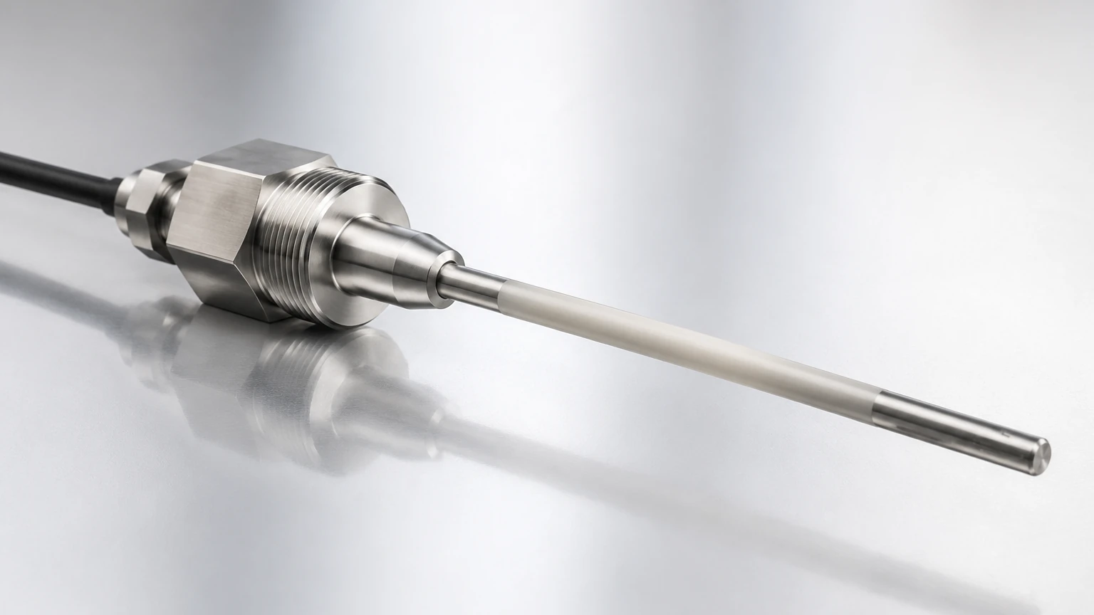
For non-metallic tanks or applications requiring high precision, a concentric design is preferred. This probe consists of a central rod housed within an outer metal tube. The fuel enters the space between the rod and the tube through small vent holes. This design ensures a consistent distance ($d$) and provides a dedicated ground reference, making the measurement independent of the tank's shape or material. It also acts as a stilling well, reducing the impact of turbulence or sloshing.
Single Rod Probes
In metallic tanks, a single insulated rod can be used, with the tank wall serving as the ground reference. However, for fuels (which are non-conductive), the rod must be precisely centered, and the tank geometry must be uniform to maintain accuracy. In most industrial B2B applications, the concentric tube design is the industry standard due to its superior stability.
Materials of Construction
* Electrode: Usually 316L stainless steel for corrosion resistance.
* Insulation: PTFE (Teflon) or PEEK is used to insulate the electrode from the mounting process and to prevent short-circuiting if the fuel contains moisture.
* Housing: Die-cast aluminum or stainless steel with IP65 to IP67 ratings to protect the electronics from environmental ingress.
Selection Criteria for Industrial Fuel Monitoring
Choosing the correct capacitance fuel probe requires an evaluation of several process parameters. Engineers should consult the Main Page of technical catalogs to compare specific model tolerances against their application requirements.
1. Dielectric Stability: The accuracy of a capacitance probe depends on a constant dielectric constant. If the fuel type changes frequently (e.g., switching between standard diesel and high-percentage biodiesel), the probe may require recalibration, as biodiesel has a different $\epsilon_r$ than petroleum diesel.
2. Tank Height and Probe Length: Probes are often custom-cut to the depth of the tank. It is essential to specify the "dead zone"—the small area at the top and bottom of the probe where measurement is not possible due to mounting hardware or end-caps.
3. Output Requirements: For integration into Building Management Systems (BMS) or Fleet Management Systems (FMS), the output signal must be compatible. Common options include 0-5V, 0-10V, 4-20mA, or RS485 (Modbus RTU).
4. Environmental Conditions: Operating temperatures can range from -40°C in arctic environments to +85°C in engine rooms. Ensure the probe’s electronics are rated for the specific ambient and process temperatures.
Technical Specifications and Selection Table
The following table outlines typical specifications for industrial-grade capacitance fuel probes used in stationary storage and mobile equipment.
| Parameter | Specification (Typical) | Notes |
| :— | :— | :— |
| Measuring Range | 100 mm to 3000 mm | Custom lengths available for deep tanks |
| Accuracy | ±0.5% to ±1.0% FS | Highly dependent on calibration |
| Input Voltage | 9V – 36V DC | Compatible with vehicle and industrial power |
| Operating Pressure | Vacuum to 0.5 MPa | Suitable for vented or low-pressure tanks |
| Process Temperature | -40°C to +100°C | High-temp versions available |
| Material | 316 Stainless Steel & PTFE | Compatible with most hydrocarbons |
| Resolution | 0.01 mm to 0.1 mm | High resolution for precise fuel accounting |
Installation Best Practices
Proper installation is paramount to the longevity and accuracy of a capacitance fuel probe. Failure to follow engineering guidelines can lead to signal noise or mechanical failure.
Position and Mounting
The probe should be mounted vertically, ideally in the center of the tank to minimize the effects of tank tilting (in mobile applications). It must be kept away from internal baffles, pumps, or agitators that could cause mechanical stress or electrical interference.
Grounding
For the capacitance circuit to function, there must be a common ground. In a concentric probe, this is handled internally. However, the housing should still be bonded to the tank or the system ground to prevent static buildup, which is a significant safety concern in fuel storage.
Calibration
Most modern probes feature a "Full" and "Empty" calibration button or wire.
* Zero Calibration: Perform this when the tank is empty or the probe is suspended in free air.
* Full Calibration: Perform this when the tank is at its maximum safe working level.
This process allows the internal microprocessor to map the capacitance range to the desired output signal (e.g., 4mA at empty and 20mA at full).
Limitations and Operating Constraints
While highly effective, the capacitance fuel probe is not a "one-size-fits-all" solution. Understanding its limitations prevents misapplication.
* Water Contamination: Water has a dielectric constant of approximately 80, while fuel is approximately 2. If water settles at the bottom of a fuel tank and reaches the probe, the capacitance will spike dramatically, leading to an artificially high level reading. Some advanced probes use this to trigger a "water-in-fuel" alarm.
* Coating and Buildup: If the fuel is heavy or prone to leaving deposits (like crude oil or heavy fuel oil), the buildup on the probe can act as a secondary dielectric layer, causing "drift" in the readings over time. Regular cleaning is required in these applications.
* Temperature Effects: Although fuel dielectric constants are relatively stable, extreme temperature shifts can cause the fuel to expand or contract, changing its density and slightly altering its electrical properties. High-precision probes often incorporate a temperature sensor for internal compensation.
Maintenance and Troubleshooting
Capacitance probes are generally low-maintenance because they have no moving parts. However, periodic checks are recommended:
1. Visual Inspection: Check for corrosion at the mounting point and ensure the vent holes in concentric probes are not clogged with sediment.
2. Signal Verification: Use a multimeter to verify that the output signal corresponds to the physical dip-tape measurement of the tank.
3. Cable Integrity: Inspect the cable entry point for signs of moisture ingress, which can cause erratic signal behavior.
Common Issue: Erratic Readings
* *Possible Cause:* Loose ground connection or electromagnetic interference (EMI) from nearby high-voltage equipment.
* *Solution:* Ensure shielded cabling is used and the shield is grounded at only one end (usually the controller end) to avoid ground loops.
Frequently Asked Questions (FAQs)
Q: Can a capacitance fuel probe be used in a plastic tank?
A: Yes, provided you use a concentric (coaxial) probe. The outer tube of the probe provides the necessary second electrode that the plastic tank wall cannot provide.
Q: Is it safe to use these probes in gasoline?
A: Yes, but the probe must be intrinsically safe (IS) or explosion-proof rated, depending on the local hazardous area classification (e.g., ATEX, IECEx).
Q: Can I cut the probe to length in the field?
A: Many industrial probes are designed to be field-cuttable. However, this requires a recalibration of the "Full" and "Empty" points immediately after cutting to account for the new electrode length.
Conclusion
The capacitance fuel probe remains a cornerstone technology for industrial fuel level monitoring due to its lack of moving parts and high sensitivity to hydrocarbon fluids. By understanding the dielectric properties of the medium and selecting the appropriate probe geometry, engineers can implement a measurement solution that offers years of reliable service. For further technical assistance and to explore a wide range of industrial level measurement instruments, please visit the Main Page to review product options and application support.