Carbon Capturing Technology
Carbon Capturing Technology
Carbon capturing technology has transitioned from a niche experimental concept to a critical industrial requirement. As global industries strive to meet stringent decarbonization targets, the deployment of Carbon Capture, Utilization, and Storage (CCS) systems has accelerated across power generation, cement manufacturing, and chemical processing. For engineers and plant managers, the success of these systems relies heavily on the precision of process control, where level measurement plays a foundational role in managing solvents, liquefied CO2, and separated waste streams.
Implementing carbon capturing technology involves complex chemical and physical phases. Whether utilizing absorption, adsorption, or membrane separation, the ability to monitor fluid levels accurately ensures system efficiency, prevents equipment damage, and maintains safety in high-pressure environments. This guide explores the technical landscape of level measurement within CCS frameworks, providing an engineering perspective on technology selection and application.
The Role of Level Measurement in Carbon Capture
In a typical post-combustion carbon capture plant, flue gas is passed through an absorber column where a solvent—usually an aqueous amine solution—binds with the CO2. The CO2-rich solvent is then pumped to a stripper column where heat is applied to release the CO2 for compression and storage.
Throughout this cycle, level measurement is indispensable for:
1. Inventory Management: Monitoring solvent levels in storage tanks and surge drums to ensure continuous operation.
2. Process Optimization: Controlling the level in absorber and stripper bottoms to maintain the liquid seal and prevent gas bypass.
3. Phase Separation: Detecting the interface between different liquid phases in separators where water or hydrocarbons may be present.
4. Safety: Preventing overfills in high-pressure CO2 storage tanks, which could lead to catastrophic vessel failure.
Measurement Principles for CCS Environments
Before selecting a specific instrument, it is essential to understand the physics behind common level measurement technologies used in carbon capturing technology applications.
Radar Level Measurement (ToF)
Radar sensors operate on the Time-of-Flight (ToF) principle. They emit high-frequency microwave pulses that travel to the product surface and reflect back to the sensor. The distance is calculated based on the time interval and the speed of light.
* Non-Contact Radar: Ideal for corrosive solvents as the sensor does not touch the medium. It is highly effective in vacuum or high-pressure conditions.
* Guided Wave Radar (GWR): Uses a physical probe to guide the microwave. This is particularly useful in applications with low dielectric constants or where heavy foam is present on the liquid surface, a common challenge in amine scrubbers.
Hydrostatic Level Measurement
This principle relies on the relationship between the height of a liquid column and the pressure it exerts at the base of a vessel. The formula $P = \rho \cdot g \cdot h$ (where $P$ is pressure, $\rho$ is density, $g$ is gravity, and $h$ is height) allows for accurate level calculation if the fluid density remains constant. In CCS, hydrostatic transmitters are often used in open or vented tanks where temperature-induced density shifts are minimal.
Ultrasonic Level Measurement
Similar to radar, ultrasonic sensors use sound waves instead of microwaves. A transducer emits an ultrasonic pulse that reflects off the liquid surface. While cost-effective for water treatment phases of a CCS plant, ultrasonic sensors are limited in carbon capture applications because changes in gas composition (high CO2 concentration) and pressure significantly alter the speed of sound, leading to measurement errors.
Magnetic Level Gauges
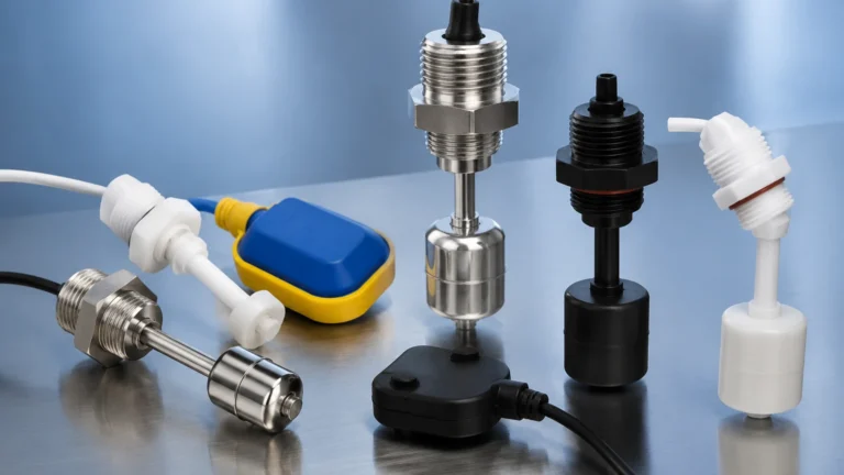
Magnetic gauges provide a visual indication and can be equipped with transmitters for remote monitoring. They utilize a float containing a magnet that moves with the liquid level, flipping external flags or triggering a reed chain transmitter. These are highly valued in CCS for their robustness in high-pressure CO2 storage vessels.
Key Applications within Carbon Capturing Technology
1. Amine Absorption Columns
The absorber is the heart of most carbon capture plants. The environment is characterized by high humidity, varying temperatures (typically 40°C to 60°C / 104°F to 140°F), and the potential for foaming. Guided Wave Radar is often the preferred choice here because the probe can penetrate foam to reach the true liquid level, ensuring the pump-out rate matches the inflow.
2. Stripper/Regenerator Units
In the stripper, the solvent is heated to approximately 100°C to 120°C (212°F to 248°F) to release CO2. This creates a turbulent, steaming environment. Non-contact radar with high-frequency (80 GHz) technology is effective here, as the narrow beam angle avoids internal obstructions like packing or sprayers, and the high frequency minimizes interference from steam.
3. CO2 Compression and Liquefaction
Once captured, CO2 is compressed and cooled into a liquid or supercritical state for transport. This involves multi-stage compressors with interstage knock-out drums. Level switches and continuous level transmitters must handle pressures exceeding 75 bar (1087 psi). Hydrostatic transmitters with specialized seals or high-pressure radar units are required to withstand these conditions.
Selection Criteria and Technical Comparison
Selecting the right instrument for carbon capturing technology requires balancing accuracy, process conditions, and maintenance requirements. For a comprehensive overview of available technologies, engineers should Review product options and application support on our Main Page.
| Feature | Non-Contact Radar | Guided Wave Radar | Hydrostatic | Magnetic Gauge |
| :— | :— | :— | :— | :— |
| Accuracy | High (±1mm) | High (±2mm) | Moderate (±0.1% FS) | Moderate |
| Pressure Range | Up to 160 bar | Up to 400 bar | Up to 400 bar | Up to 250 bar |
| Temp. Range | -40 to +450°C | -200 to +450°C | -40 to +100°C | -196 to +400°C |
| Foam Resistance | Moderate | Excellent | Good | Excellent |
| Maintenance | Very Low | Low | Moderate | Low |
| Installation | Top-mounted | Top-mounted | Bottom/Side | Side-mounted |

Installation and Engineering Considerations
Successful deployment of level sensors in CCS projects requires attention to specific mechanical and chemical factors:
* Material Compatibility: Amine solvents can be corrosive to certain elastomers and metals. 316L Stainless Steel is standard, but for aggressive solvents, Hastelloy or PTFE coatings may be necessary for wetted parts.
* Nozzle Geometry: For radar installations, the nozzle height and diameter must be designed to prevent signal interference. A taller nozzle may require a horn antenna or a wave-guide to ensure the signal clears the vessel wall.
* Supercritical CO2 Challenges: When CO2 reaches its supercritical state (above 31.1°C and 73.8 bar), the boundary between liquid and gas disappears. In these specialized storage applications, mass-based measurement or specialized density-compensated hydrostatic systems are often used alongside level instruments.
* Vapor Space Compensation: In high-pressure gas phases, the dielectric constant of the gas increases. This can slow down radar pulses. High-end radar transmitters include software algorithms to compensate for this "gas phase effect," ensuring accuracy remains within 1-2%.
Challenges and Limitations
While modern instrumentation is highly capable, carbon capturing technology presents unique hurdles:
1. Foaming: In amine systems, impurities can cause significant foaming. If a non-contact sensor is used, the foam may absorb the signal, leading to a "loss of echo." GWR or displacement-based sensors are better suited for these scenarios.
2. Build-up: Some carbon capture processes involve slurries or solids (such as in calcium looping). Material build-up on probes can cause false readings. Non-contact radar is the primary solution for these "dirty" applications.
3. Extreme Pressures: CO2 transport pipelines and injection wells operate at extremely high pressures. Standard industrial level meters may not have the required pressure ratings, necessitating specialized oil-and-gas grade instrumentation.
FAQs
Q: Can ultrasonic sensors be used for liquefied CO2 storage?
A: It is not recommended. The high pressure and the specific vapor composition of CO2 significantly alter the speed of sound, which would require constant, complex recalibration that is rarely accurate enough for industrial safety standards.
Q: How does temperature affect level measurement in the stripper column?
A: In hydrostatic systems, as temperature increases, the density of the solvent decreases. If the transmitter is not density-compensated, it will report a lower level than actually exists. Radar is generally unaffected by these temperature-induced density changes.
Q: What is the best way to measure the interface between solvent and water?
A: Guided Wave Radar (GWR) is the industry standard for interface measurement. It can detect the first reflection from the upper liquid (low dielectric) and a second reflection from the interface with the lower liquid (high dielectric), provided the upper layer is non-conductive.
Q: Is maintenance required for radar sensors in CCS?
A: Non-contact radar is virtually maintenance-free because it has no moving parts and does not touch the medium. However, periodic verification of the electronics and checking the antenna for any condensed buildup is recommended during scheduled plant shutdowns.
Conclusion
As carbon capturing technology continues to evolve, the demand for precise, reliable instrumentation will only grow. By understanding the principles of radar, hydrostatic, and magnetic measurement, engineers can design CCS systems that are not only efficient but also resilient to the harsh conditions of CO2 processing. Selecting the correct technology—taking into account pressure, temperature, and chemical compatibility—is the first step toward a successful decarbonization strategy. For detailed technical specifications and customized solutions for your specific CCS project, visit our Main Page to explore our full range of industrial level measurement instruments.