Carbon Dioxide Capture and Storage
Carbon Dioxide Capture and Storage
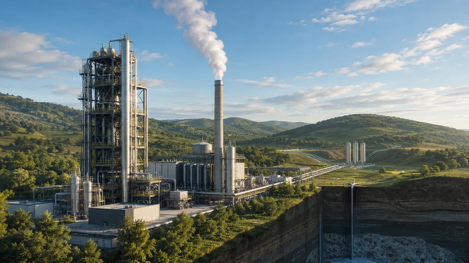
Carbon dioxide capture and storage (CCS) represents a critical suite of technologies designed to mitigate the impact of industrial emissions on the global climate. By capturing CO2 at the source—such as power plants, cement kilns, and steel mills—and transporting it for permanent underground sequestration, industries can significantly reduce their carbon footprint. Within these complex systems, the precise monitoring of liquid and gaseous CO2 levels is essential for process efficiency, safety, and regulatory compliance.
In the engineering of CCS infrastructure, level measurement instruments must withstand high pressures, fluctuating temperatures, and the unique physical properties of carbon dioxide. This guide examines the measurement principles, selection criteria, and installation requirements for level instrumentation used in carbon dioxide capture and storage applications.
Measurement Principles for CO2 Applications
Before selecting a specific instrument for a CCS project, it is vital to understand the physics of the measurement technologies. Carbon dioxide presents unique challenges, particularly its low dielectric constant (approximately 1.6 in liquid form) and its tendency to exist in a supercritical state under specific pressure and temperature conditions.
Radar Level Measurement (Non-Contact)
Non-contact radar transmitters utilize high-frequency microwave pulses (typically in the 80 GHz range) emitted from an antenna. These pulses reflect off the surface of the CO2 and return to the sensor. The time-of-flight (ToF) is used to calculate the distance.
* Principle: Microwaves travel at the speed of light. The distance is calculated as $D = (c \times t) / 2$.
* CCS Relevance: Because it is non-contact, it is unaffected by the density changes of the CO2. However, the low dielectric constant of CO2 means the reflected signal is weak, requiring high-sensitivity 80 GHz radar units to ensure a reliable echo.
Guided Wave Radar (GWR)
Guided Wave Radar operates on the same time-of-flight principle but directs the microwave pulse along a physical probe (rod or cable).
* Principle: The probe guides the energy, concentrating it and reducing signal attenuation. When the pulse hits the liquid CO2, a portion of the energy is reflected due to the change in dielectric constant.
* CCS Relevance: GWR is often superior for liquid CO2 storage because the probe ensures a stronger return signal despite the low dielectric constant. It is also highly effective in bypass chambers or stilling wells.
Hydrostatic Level Measurement
Hydrostatic transmitters measure the pressure exerted by the liquid column at the bottom of a vessel.
* Principle: Level is calculated using the formula $P = \rho \times g \times h$, where $P$ is pressure, $\rho$ is density, $g$ is gravity, and $h$ is height.
* CCS Relevance: This is a reliable method for mass-based inventory. However, in CCS, CO2 density changes significantly with temperature and pressure. Therefore, hydrostatic systems must be compensated with real-time temperature and pressure data to maintain accuracy.
Ultrasonic Level Sensors
Ultrasonic sensors emit sound waves that reflect off the liquid surface.
* Principle: The sensor measures the time taken for the sound pulse to return.
* CCS Relevance: While cost-effective, ultrasonic sensors are generally not recommended for high-pressure CO2 storage. Changes in the gas composition and pressure above the liquid significantly alter the speed of sound, leading to substantial errors.
Selecting Level Instruments for CCS Stages
The carbon dioxide capture and storage process is divided into three primary stages: capture, transport, and storage. Each stage requires specific instrumentation tailored to the environment.
1. The Capture Stage
In the capture stage, CO2 is typically absorbed into a solvent (like amines) in an absorption tower.
* Requirement: Level sensors must monitor the solvent level in the sump of the absorber and the regenerator.
* Recommendation: Hydrostatic transmitters with chemical-resistant diaphragms or Guided Wave Radar are preferred here. The presence of foam in amine towers can interfere with non-contact radar, making GWR a more stable choice.
2. The Transport Stage
Captured CO2 is compressed into a liquid or supercritical state for transport via pipelines or ships.
* Requirement: High-pressure vessels and surge tanks require continuous level monitoring to prevent overfilling and pump cavitation.
* Recommendation: High-pressure rated GWR or Magnetic Level Gauges (MLG) with integrated transmitters are ideal. MLGs provide a local visual indication which is critical for manual safety checks during loading and unloading.
3. The Storage Stage
CO2 is injected into deep geological formations. Before injection, it is often held in large surface storage tanks.
* Requirement: High accuracy for inventory management and leak detection.
* Recommendation: 80 GHz non-contact radar is the standard for large storage tanks, as it provides high precision without requiring internal probes that might be difficult to maintain in massive vessels.
Technical Comparison and Selection Table
When evaluating instruments for a CCS project, engineers should compare the following parameters:
| Technology | Accuracy | Pressure Range | Dielectric Sensitivity | Best Use Case |
| :— | :— | :— | :— | :— |
| 80 GHz Radar | ±1 mm | Up to 160 bar | High Sensitivity Required | Large Storage Tanks |
| Guided Wave Radar | ±2 mm | Up to 400 bar | Excellent | High-Pressure Process Vessels |
| Hydrostatic | ±0.1% Span | Unlimited | Insensitive | Mass/Inventory Balance |
| Magnetic Gauge | ±5 mm | Up to 320 bar | Insensitive | Visual Safety Monitoring |
| Ultrasonic | ±0.25% Span | Low Pressure Only | Insensitive | Atmospheric Water Tanks |
For a comprehensive look at available hardware and technical specifications, engineers should Review product options and application support to ensure the selected device meets the specific pressure and temperature ratings of their facility.
Installation and Engineering Considerations
Successful implementation of level measurement in carbon dioxide capture and storage depends heavily on proper installation. Given the volatile nature of CO2, several engineering factors must be addressed:
Pressure and Temperature Ratings
CO2 is often stored at pressures exceeding 50 bar and temperatures as low as -50°C (for refrigerated liquid storage). All level instruments, including seals, gaskets, and housings, must be rated for these extremes. Welk's industrial-grade sensors are designed to maintain integrity under these cyclic thermal and pressure loads.
Material Compatibility
While CO2 itself is not highly corrosive to carbon steel in a dry state, the presence of moisture can lead to the formation of carbonic acid. In the capture stage, solvents like amines can also be aggressive. Stainless steel (316L) is the minimum recommended material for wetted parts, with Hastelloy or PTFE coatings used in more corrosive capture environments.
Nozzle and Standoff Design
For radar and ultrasonic sensors, the nozzle height and diameter must be designed to prevent signal interference. If a nozzle is too long or narrow, the radar beam may reflect off the nozzle walls rather than the CO2 surface. Using an 80 GHz radar helps mitigate this due to its narrow beam angle (typically 3° to 8°).
Bypass Chambers and Stilling Wells
In vessels with high turbulence or foam, installing the level sensor (GWR or Radar) inside a bypass chamber or stilling well is highly recommended. This provides a calm surface for measurement and allows for maintenance without depressurizing the main vessel.
Limitations and Operating Challenges
Despite advances in technology, carbon dioxide capture and storage applications present specific limitations that must be managed:
1. Supercritical Transitions: Near the critical point (31.1°C and 73.8 bar), the boundary between liquid and gas disappears. In this state, traditional surface-based level measurement (Radar, Ultrasonic) becomes impossible because there is no distinct interface to reflect the signal. In these cases, mass flow or hydrostatic pressure is used to infer the state of the vessel.
2. Boil-off and Vapor Clouds: Rapid temperature changes can cause CO2 to boil, creating a dense vapor layer. This vapor can attenuate radar signals or change the speed of sound for ultrasonic sensors. GWR is the most resilient technology in these conditions.
3. Build-up and Scaling: In the capture stage, solvent degradation products can build up on probes. Regular maintenance and the use of non-contact sensors or self-cleaning probe designs are necessary to prevent measurement drift.
Frequently Asked Questions (FAQ)
Q: Can I use a standard water level sensor for liquid CO2?
A: Generally, no. Liquid CO2 has a much lower dielectric constant than water (~1.6 vs ~80) and is stored at significantly higher pressures. A standard sensor will likely fail to detect the surface or suffer mechanical failure due to pressure.
Q: How does temperature affect hydrostatic level measurement in CCS?
A: CO2 density is highly sensitive to temperature. If the temperature drops, the density increases, which would cause a hydrostatic transmitter to report a higher level than actually exists unless the system is density-compensated.
Q: Is 80 GHz radar better than 26 GHz for CO2?
A: Yes. The 80 GHz frequency allows for a much smaller antenna and a narrower beam, which results in a stronger return signal from low-dielectric liquids like CO2 and better avoidance of internal tank obstructions.
Q: What is the role of level switches in CCS?
A: Level switches (such as vibrating forks or thermal dispersion switches) act as independent high-level alarms. They provide a critical layer of protection to prevent tank overfill, which is a major safety requirement in industrial gas handling.
Conclusion
As the global industrial sector scales up carbon dioxide capture and storage initiatives, the demand for reliable, high-precision level instrumentation continues to grow. Choosing the right measurement principle—whether it be the robust signal of Guided Wave Radar for process vessels or the high-precision non-contact radar for storage tanks—is fundamental to the success of these projects.
Engineers must account for the unique physical properties of CO2, including its low dielectric constant and phase behavior, while ensuring all hardware meets stringent pressure and temperature requirements. For detailed technical specifications and to find the most suitable instrumentation for your specific CCS application, please visit the Main Page of our product catalog. By integrating advanced level measurement solutions, operators can ensure that their carbon capture processes remain safe, efficient, and compliant with evolving environmental standards.