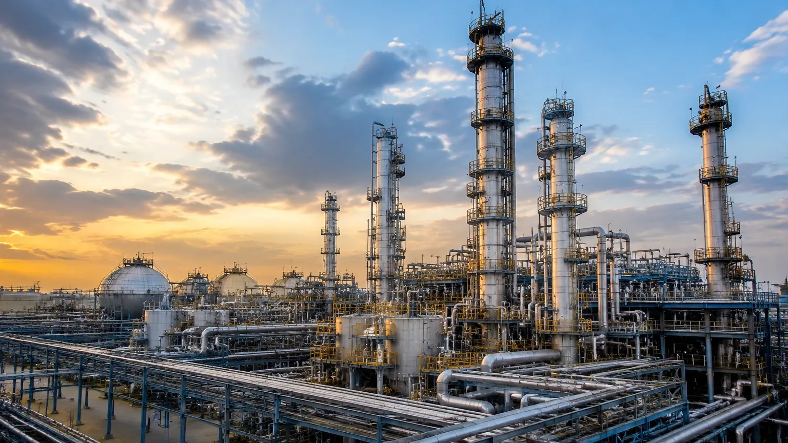
Chemical Facility
Chemical Facility
In the complex ecosystem of a chemical facility, precise level measurement is not merely a matter of inventory management; it is a fundamental requirement for operational safety, process efficiency, and environmental compliance. Chemical processing involves a diverse array of substances, ranging from benign water-based solutions to highly corrosive acids, volatile solvents, and viscous polymers. Each of these substances presents unique challenges to instrumentation, requiring engineers to move beyond a one-size-fits-all approach to level sensing.
Selecting the appropriate level measurement technology for a chemical facility requires a deep understanding of the physical and chemical properties of the media, the dynamics of the process vessel, and the environmental conditions of the plant. This guide explores the primary measurement principles utilized in modern chemical processing and provides practical frameworks for instrument selection and installation.
Measurement Principles for Chemical Applications
Before recommending a specific instrument, it is essential to understand the physics behind the most common level measurement technologies used in the industry. Each principle interacts differently with the chemical media and the headspace of the tank.
Radar Level Measurement (FMCW and Pulse)
Radar technology is widely considered the gold standard for many applications within a chemical facility. It operates on the principle of Time of Flight (ToF). The instrument emits electromagnetic waves that travel to the surface of the liquid and reflect back to the sensor.
* Non-Contact Radar: This type is ideal for corrosive or sterile environments because the sensor does not touch the medium. Frequency Modulated Continuous Wave (FMCW) radar is particularly effective, as it uses a continuous signal with a varying frequency to provide high-precision measurements even in the presence of vapors or light foam.
* Guided Wave Radar (GWR): GWR uses a physical probe (a cable or rod) to guide the microwave signal. This is highly effective for liquids with low dielectric constants or processes with heavy turbulence, as the probe focuses the energy and ensures a strong return signal.
Ultrasonic Level Sensors
Ultrasonic sensors also use the ToF principle but utilize sound waves instead of electromagnetic waves. While cost-effective and reliable for many water-treatment applications within a chemical facility, they have limitations. Sound speed is affected by air temperature, pressure, and the composition of the gas in the tank's headspace. Consequently, ultrasonic sensors are often avoided in tanks containing volatile chemicals where solvent vapors can significantly alter the speed of sound.
Hydrostatic Level Transmitters
Hydrostatic measurement relies on the principle that the pressure at the bottom of a vessel is proportional to the height of the liquid column above it. The formula $P = \rho \cdot g \cdot h$ (where $P$ is pressure, $\rho$ is density, $g$ is gravity, and $h$ is height) governs this measurement. In a chemical facility, hydrostatic sensors must be carefully selected based on material compatibility. Diaphragms are often coated with PTFE or made from exotic alloys like Hastelloy to resist corrosion.
Magnetic Level Gauges
Magnetic level gauges provide both a visual indication and, when equipped with a transmitter, a continuous electronic signal. They consist of a bypass chamber connected to the side of the vessel. A float containing a magnet moves with the liquid level, flipping bicolored flaps on an external scale. This technology is favored for high-pressure and high-temperature applications where glass gauges would be a safety risk.
Selecting Level Instruments for a Chemical Facility
Choosing the right instrument involves evaluating the specific constraints of the chemical facility. Failure to account for even one variable can lead to premature sensor failure or dangerous inaccuracies.
Chemical Compatibility and Material Selection
The most critical factor is the compatibility of the wetted parts with the process media. In a chemical facility, instruments are often exposed to:
* Strong Acids and Bases: Requiring PVDF, PTFE, or PFA coatings.
* Organic Solvents: Which can degrade certain elastomers and plastics.
* Abrasive Slurries: Requiring hardened metals or ceramic diaphragms.
Process Conditions
Engineers must confirm the maximum and minimum operating pressures and temperatures. For example, while an ultrasonic sensor might fail at temperatures above 80°C (176°F), a high-frequency radar or a magnetic level gauge can operate effectively at several hundred degrees Celsius. Similarly, vacuum conditions can cause certain sensor diaphragms to distend, requiring specialized vacuum-resistant designs.
Tank Geometry and Obstructions
The internal structure of a tank in a chemical facility often includes agitators, heating coils, and baffles. Non-contact radar requires a clear "line of sight" to the liquid surface. If obstructions are present, Guided Wave Radar or the use of a stilling well may be necessary to prevent false echoes from interfering with the level reading. For more detailed technical specifications on how these instruments integrate into complex systems, engineers can refer to the Main Page for comprehensive product data.
Practical Selection Table
The following table provides a general comparison of technologies based on common requirements found in a chemical facility.
| Technology | Best For | Limitations | Chemical Resistance |
| :— | :— | :— | :— |
| Non-Contact Radar | Volatile liquids, corrosive acids, high precision. | High initial cost compared to ultrasonic. | Excellent (Non-contact). |
| Guided Wave Radar | Low dielectric liquids, turbulent surfaces. | Probe can be coated by viscous media. | High (Depends on probe material). |
| Ultrasonic | Water-based chemicals, open sumps. | Vapors, foam, and high pressure. | Moderate (Plastic housings). |
| Hydrostatic | Vented tanks, constant density liquids. | Sensitive to density changes. | High (With alloy diaphragms). |
| Magnetic Gauge | High pressure/temp, visual redundancy. | Moving parts can wear; bypass piping required. | High (Stainless/Alloy chambers). |
Installation Considerations and Best Practices
Correct installation is as important as instrument selection. In a chemical facility, improper mounting can lead to signal loss or physical damage to the sensor.
1. Nozzle Dimensions: For radar and ultrasonic sensors, the mounting nozzle should be as short and wide as possible to prevent "ringing" or interference from the nozzle walls.
2. Dead Zones (Blocking Distance): Every ToF sensor has a minimum distance it cannot measure (the dead zone). Ensure the sensor is mounted high enough that the maximum liquid level never enters this zone.
3. Agitation and Turbulence: In tanks with heavy agitation, the liquid surface is rarely flat. Using a stilling well or a bypass pipe can provide a calm surface for the sensor to measure, ensuring a stable output for the control system.
4. Positioning: Avoid mounting sensors directly above the tank inlet. The falling stream of liquid will cause false readings and can physically damage the sensor over time.
Limitations and Common Risks in Chemical Environments
Operating in a chemical facility introduces risks that are less prevalent in other industries. Awareness of these limitations is vital for risk mitigation.
Vapor and Gas Layers
In many chemical processes, the headspace of a tank is not filled with air but with a concentrated vapor or a nitrogen blanket. These gases can attenuate ultrasonic signals or change the dielectric constant of the medium in the headspace, affecting radar propagation speeds. High-frequency FMCW radar (e.g., 80 GHz) is typically the most resilient to these effects.
Foam Formation
Foam is a common byproduct of chemical reactions or mixing. Depending on the density and thickness of the foam, it can either absorb a radar signal (leading to signal loss) or reflect it (leading to a false "high" reading). Guided wave radar is often the preferred solution for heavy foam, as the signal is concentrated along the probe.
Hazardous Area Classifications
Most areas within a chemical facility are classified as hazardous (Ex/ATEX zones). Instruments must be certified for use in these areas. This usually involves choosing between Intrinsically Safe (Ex i) circuits, which limit the electrical energy available for ignition, or Explosion-Proof (Ex d) housings, which are designed to contain an internal explosion.
Frequently Asked Questions (FAQs)
Q: How does the dielectric constant ($ε_r$) affect radar measurement?
A: The dielectric constant determines how much of the radar signal is reflected. Water has a high $ε_r$ (~80) and reflects signals strongly. Hydrocarbons and solvents often have low $ε_r$ (<2), which means much of the signal passes through the liquid rather than reflecting. In these cases, Guided Wave Radar or high-sensitivity non-contact radar is required.
Q: Can hydrostatic sensors be used if the liquid density changes?
A: Hydrostatic sensors measure the weight of the liquid, not the actual height. If the density changes due to temperature fluctuations or concentration changes, the level reading will be inaccurate unless the control system can compensate for the density shift in real-time.
Q: What is the benefit of an 80 GHz radar over a 26 GHz radar in a chemical facility?
A: 80 GHz radar has a much narrower beam angle. This makes it easier to install in tanks with internal obstructions and allows for better performance in small nozzles, which are common in chemical vessels.
Conclusion
Successful level measurement in a chemical facility depends on a rigorous evaluation of the process environment and the chemical properties of the media. By understanding the strengths and limitations of radar, ultrasonic, hydrostatic, and magnetic technologies, engineers can implement solutions that enhance safety and optimize production. For those seeking specific hardware configurations or customized OEM/ODM services for industrial automation, visiting the Main Page provides access to a wide range of professional measurement instruments designed for the rigors of the chemical industry.