Cip Optimize
Cip Optimize
In the modern industrial landscape, particularly within the food and beverage, pharmaceutical, and chemical processing sectors, Clean-In-Place (CIP) systems are fundamental to maintaining hygiene and product integrity. To cip optimize is to refine these automated cleaning processes to reduce cycle times, minimize the consumption of water and expensive chemicals, and lower energy usage without compromising sterilization standards. Achieving this balance requires a high degree of precision in process monitoring, where level measurement instrumentation plays a pivotal role.
Effective CIP optimization relies on the ability to monitor storage tanks, balance tanks, and chemical recovery systems with extreme accuracy. When sensors provide real-time, reliable data, plant operators can transition from time-based cleaning cycles to sensor-based cycles, ensuring that resources are only used when necessary. This article explores the technical principles of level measurement in CIP environments and provides an engineering framework for selecting and installing the correct instrumentation to achieve a fully optimized system.
Understanding Clean-In-Place (CIP) Systems
A CIP system typically consists of several tanks containing fresh water, deionized water, caustic detergents, and acid sanitizers. These fluids are pumped through the production equipment—such as pipes, heat exchangers, and fermentation vessels—at specific temperatures and flow rates. The process usually follows a sequence: pre-rinse, caustic wash, intermediate rinse, acid wash, and final rinse.
To cip optimize, engineers must look at the "four T’s" of cleaning: Time, Temperature, Titration (chemical concentration), and Turbulence (mechanical force). Level measurement directly influences the efficiency of these variables by ensuring that tanks never run dry (preventing pump cavitation), managing the precise dosing of concentrates, and monitoring the recovery of expensive cleaning agents for reuse.
Measurement Principles in CIP Environments
Before selecting a device for CIP optimization, it is essential to understand how different measurement technologies interact with the harsh conditions of a cleaning cycle, which often involve steam, high-pressure sprays, and corrosive chemicals.
1. Radar Level Measurement (Non-Contact)
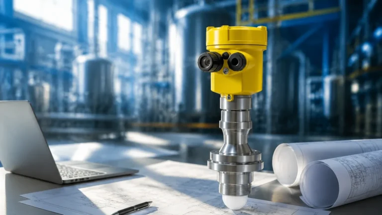
Radar transmitters, particularly those operating at high frequencies like 80 GHz, utilize the Time-of-Flight (ToF) principle. The sensor emits a microwave signal that reflects off the liquid surface and returns to the receiver. The distance is calculated based on the time taken for the signal to travel.
In a CIP context, radar is highly valued because it is non-contact. The sensor does not touch the corrosive caustic or acid, reducing maintenance. Modern radar units can "see through" heavy steam and ignore the presence of agitators or spray balls via advanced signal processing and false-echo suppression.
2. Ultrasonic Level Measurement
Ultrasonic sensors also use ToF but rely on sound waves rather than electromagnetic waves. While cost-effective, they are generally less suitable for high-temperature CIP cycles. Sound velocity changes with air temperature, and the dense steam generated during a hot caustic wash can deflect or absorb the sound signal, leading to inaccuracies. They are best reserved for ambient temperature water storage tanks within the CIP utility area.
3. Hydrostatic Pressure Measurement
Hydrostatic sensors measure the pressure exerted by the liquid column at the bottom of the tank. This pressure is directly proportional to the liquid height and density. For CIP applications, these sensors must feature a flush-mounted diaphragm to prevent "dead legs" where bacteria could grow. They are robust but require recalibration if the density of the cleaning fluid changes significantly (e.g., switching from water to a dense caustic concentrate).
4. Capacitance and Conductivity Switches
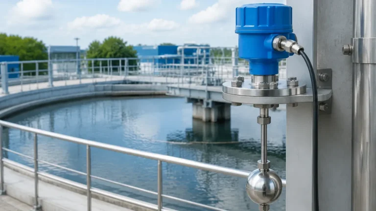
These are point-level sensors used to detect the presence or absence of liquid at specific heights. Conductivity switches are particularly useful in CIP systems to detect the interface between cleaning chemicals and rinse water, allowing for precise diverted flow to recovery tanks.
Strategies to Cip Optimize via Precision Instrumentation
Optimization is achieved when the measurement data allows for the reduction of waste. Here is how specific level measurement strategies contribute to an optimized CIP process:
* Chemical Recovery: By using accurate level sensors in recovery tanks, plants can maximize the reuse of detergents. If a sensor can detect the difference between the final rinse water and the initial caustic return, the system can automatically divert the usable chemical back into the supply tank rather than the drain.
* Reduced Water Consumption: Precise level monitoring in balance tanks prevents overfilling and allows for the use of the minimum required volume for a successful rinse. Even a 5% reduction in water use per cycle can result in thousands of cubic meters saved annually.
* Energy Efficiency: Heating large volumes of water and chemicals to 80°C or higher is energy-intensive. By optimizing tank levels to the exact volume needed for the equipment's internal surface area, the energy required for heating is minimized.
* Downtime Reduction: Reliable sensors prevent false "empty" or "full" readings that can trigger emergency stops or manual interventions. This ensures the cleaning cycle completes as fast as possible, allowing the plant to return to production.
For a comprehensive look at the various instruments available for these applications, engineers can visit the Main Page to review technical specifications and compatibility charts.
Technical Selection Criteria for Hygienic Level Sensors
When selecting a level meter to cip optimize a facility, the following criteria must be evaluated to ensure the device can withstand the rigors of the process:
Material Compatibility
The wetted parts of the sensor must be resistant to the chemicals used. Typically, 316L stainless steel is the standard for housings and diaphragms. For highly corrosive acids, coatings such as PTFE (Polytetrafluoroethylene) or PEEK (Polyether ether ketone) are required to prevent pitting and corrosion.
Surface Finish and Hygiene Standards
In B2B food and pharma applications, the sensor must meet international hygiene standards such as 3-A or EHEDG. This means the surface roughness (Ra) must be less than 0.8 μm to prevent microbial attachment. The design must be free of crevices and sharp corners.
Temperature and Pressure Ratings
CIP cycles often involve "Thermal Shock," where a cold rinse immediately follows a hot wash. Sensors must be rated for temperatures up to at least 130°C (for SIP – Sterilization-In-Place) and be able to handle the vacuum pressures that can occur when steam condenses rapidly inside a sealed vessel.
Selection Table for CIP Level Measurement
| Technology | Best Use Case | Pros | Cons |
| :— | :— | :— | :— |
| 80GHz Radar | Process Vessels & Storage | Non-contact, ignores steam/foam, high precision | Higher initial cost |
| Hydrostatic | Balance Tanks | Reliable, simple to install, measures mass | Sensitive to density changes |
| Ultrasonic | Raw Water Storage | Cost-effective, non-contact | Fails in steam/high temp |
| Capacitive | Interface Detection | Fast response, detects chemical change | Requires contact with fluid |
| Level Switch | Overfill Protection | High reliability, safety redundant | Point level only, no continuous data |

Installation Best Practices for CIP Compliance
Even the most advanced sensor will fail to provide data for CIP optimization if installed incorrectly. Engineers should adhere to the following guidelines:
1. Avoid Dead Legs: A dead leg is an area in the piping or tank where fluid can stagnate and avoid the cleaning spray. Sensors should be installed using hygienic fittings like Tri-Clamps or Varivent® flanges that allow the sensor face to be flush with the tank wall.
2. Positioning Relative to Spray Balls: Non-contact sensors like radar should be positioned so that the signal beam does not intersect with the path of the CIP spray balls. If the spray hits the sensor lens directly during a measurement cycle, it may cause a momentary loss of signal.
3. Mounting Angle: For hydrostatic sensors, ensure the diaphragm is mounted at a point where it will not be covered by sediment or sludge. For radar, the sensor must be mounted perfectly vertical to ensure the return signal is received.
4. Cable Protection: In the wash-down environment of a CIP room, IP68 or IP69K rated housings and connectors are mandatory. The cabling should be protected by stainless steel conduits to prevent chemical ingress.
Limitations and Operational Challenges
While technology has advanced, certain limitations remain when trying to cip optimize a system:
* Foam Interference: Heavy, dense foam (common in caustic washes) can absorb radar and ultrasonic signals. Selecting a radar with a high dynamic range or using a bypass pipe (stilling well) can mitigate this, though bypass pipes are harder to clean.
* Condensation: In high-humidity environments, water droplets can form on the sensor lens. While 80 GHz radar can often see through small droplets, a heavy buildup can attenuate the signal. Some sensors feature a convex lens design to encourage droplets to run off.
* Signal Noise: In small vessels with internal ladders, agitators, and heating coils, signal reflections can become complex. Software-based "envelope curves" and background subtraction are necessary to filter out these obstructions.
Frequently Asked Questions (FAQ)
Q: How often should CIP level sensors be calibrated?
A: For hydrostatic sensors, annual calibration is recommended due to potential diaphragm drift. Non-contact radar sensors are generally more stable and may only require verification every 24 months, depending on the criticality of the process.
Q: Can one sensor handle both the cleaning cycle and the production cycle?
A: Yes, provided the sensor is rated for the maximum temperature and pressure of both cycles. This is a key part of how plants cip optimize, as it reduces the number of tank penetrations required.
Q: Does the dielectric constant of the cleaning fluid affect radar measurement?
A: Radar requires a reflection from the surface. Most CIP fluids are water-based and have a high dielectric constant (εr > 20), making them excellent targets for radar. However, very pure deionized water has a lower dielectric constant and may require more sensitive sensor settings.
Q: What is the benefit of IO-Link in CIP optimization?
A: IO-Link allows for digital communication between the sensor and the PLC. It can transmit not just the level, but also the internal temperature of the sensor and diagnostic data. This enables predictive maintenance, ensuring a sensor is replaced before it fails during a critical cleaning cycle.
Conclusion
To effectively cip optimize an industrial cleaning process, the integration of high-precision level measurement is non-negotiable. By moving away from manual checks and time-based estimates toward a data-driven approach, facilities can realize significant savings in water, chemicals, and energy. Whether utilizing the non-contact advantages of 80 GHz radar or the robust reliability of hydrostatic pressure transmitters, selecting the right tool for the specific environmental conditions is the first step toward operational excellence.
For technical assistance in selecting the appropriate instrumentation for your specific application, or to explore our full range of industrial level meters, please refer to the Main Page for detailed product documentation and engineering support.